background image

60 


2.


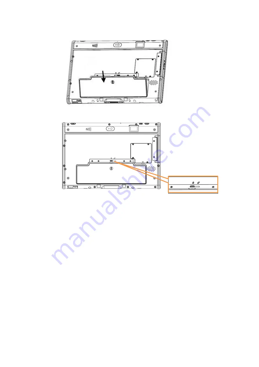
Lock to secure the battery once it is properly to be inserted.   


A.2.1.2 Removing the External Battery 

Repeat the above steps in reverse order to remove the battery. 

A.2.2 Office Docking Station 

You can use the office docking stand to dock the MIT-M101 when you are at your 
home or on your office desk. When docked, you can charge both the internal and 
external batteries or transfer data from your MIT-M101 to another PC. 


Summary of Contents for MIT-W102 Series

Page 1: ...1 Mobile Computer MIT W102XXXXXXXXXXXXXXXX User Manual Ver 1 1 MIT W102 ...

Page 2: ...Advantech Co Ltd assumes no responsibility for its use nor for any infringements of the rights of third parties which may result from its use Acknowledgements All other product names or trademarks are properties of their respective owners Intended use The MIT W102 is intended for integration with hospital system It is designed for general purpose for hospital environment For data collection and di...

Page 3: ...ice may not cause harmful interference 2 This device must accept any interference received including interference that may cause undesired operation The WLAN BT function of this product uses a certified module and according to FCC regulations contains RF module FCC ID PPD QCNFA364AH IC 4104A QCNFA364A or FCC ID TX2 RTL8822CE IC 6317A RTL8822CE CAUTION Exposure to Radio Frequency Radiation The radi...

Page 4: ...ged to try to correct the interference by one or more of the following measures Reorient or relocate the receiving antenna Increase the separation between the equipment and receiver Connect the equipment into an outlet on a circuit different from that to which the receiver is connected Consult the dealer or an experienced computer technician for help Warning Any changes or modifications made to th...

Page 5: ...re are for air convection Protect the equipment from overheating DO NOT COVER THE OPENINGS 8 Do not leave this equipment in an environment unconditioned where the storage temperature under 20 C or above 60 C it may damage the equipment 9 Make sure the voltage of the power source is correct before connecting the equipment to the power outlet 10 Place the power cord such a way that people cannot ste...

Page 6: ...cording to the manufacturer s instructions 18 CLASSIFICATION Supply Class I adapter No applied part Continuous Operation Not AP or APG category 19 Disconnect device disconnect the power cord and battery to fully power off the device 20 Do not place the power cord where it is difficult to disconnect and may be stepped by other persons 21 Follow national state or local requirements to dispose of uni...

Page 7: ...rization of the manufacturer 30 WARNING To avoid risk of electric shock this equipment must only be connected to a supply mains with protective earth 31 WARNING Please avoid having enclosure to contact with skin more than 1 minute 32 CAUTION This product MIT W102 is used with the Qualified and certificated power adapter Delta ELECTRONICS CO LTD model MDS 060AAS19 B Output 19Vdc 3 15A max DISCLAIME...

Page 8: ...uit 11 Tous les avertissements et avertissements sur l équipement doivent être notés 12 Si l équipement n est pas utilisé pendant une longue période débranchez le de la source d alimentation pour éviter d être endommagé par une surtension transitoire 13 Ne versez jamais de liquide dans les ouvertures de ventilation Cela pourrait provoquer un incendie ou un choc électrique 14 N ouvrez jamais l équi...

Page 9: ...ion et la batterie pour éteindre complètement l appareil 20 Ne placez pas le cordon d alimentation à un endroit où il est difficile de le déconnecter et où d autres personnes pourraient marcher dessus 21 Respectez les exigences nationales régionales ou locales pour éliminer l unité 22 Entretien pour bien entretenir et nettoyer les surfaces n utiliser que les produits approuvés ou nettoyer avec un ...

Page 10: ...e selon la CEI 704 1 1982 n excède pas 70 dB A 29 AVERTISSEMENT Ne modifiez pas cet équipement sans l autorisation du fabricant 30 AVERTISSEMENT Pour éviter tout risque d électrocution cet équipement ne doit être connecté qu à une alimentation secteur avec terre de protection 31 AVERTISSEMENT veuillez éviter tout contact du boî tier avec la peau pendant plus d une minute 32 ATTENTION Ce produit MI...

Page 11: ...m Ion battery pack The process is more efficient at normal room temperature or slightly cooler It is essential that you charge batteries within the stated range of 0 C to 35 C Charging batteries outside of the specified range could damage the batteries and shorten their charging life cycle Storage and Safety Notice Although charge Lithium Ion batteries may be left unused for several months their c...

Page 12: ... Connecting USB Devices 24 2 4 Connecting Headphones 24 2 5 Connecting a Microphone 25 Chapter 3 Turning On 26 3 1 Controlling the MIT W102 27 3 1 1 Using the Touch Screen 27 3 1 2 Using the Tap Function 27 3 1 3 Using the Control Panel Buttons 27 3 1 4 Using the On Screen Keyboard 28 3 1 5 Adjusting Screen Brightness 31 3 1 6 Adjusting the Volume 32 Chapter 4 Wireless Connections 33 4 1 Wi Fi Con...

Page 13: ...etting 47 6 1 Dashboard 48 6 2 NFC 48 6 2 1 NFC application 48 6 2 2 NFC Setting 49 6 2 3 NFC Usage 51 6 3 Camera 51 6 4 Brightness 54 6 5 Hotkey Setting 55 Appendix Specifications 56 A 1 Specifications 57 A 2 Optional Accessories 59 A 2 1 External Battery 59 A 2 2 Office Docking Station 60 A 2 3 VESA Docking Station 64 A 2 4 Adjustable Stand with the hand strap 66 A 2 5 Rubber Bumper 69 A 3 Insta...

Page 14: ...nes rugged design with reliable performance and powerful functionality to best suit all your needs in a wide range of working conditions This user manual outlines all you need to know to set up and use your MIT W102 If you have any further questions or queries contact our technical support team via our website ...

Page 15: ...eaturing with the Future Intel Pentium processor for intelligent system Built in WLAN Bluetooth NFC Durable shock resistant magnesium alloy housing 10 1 WUXGA TFT LCD Power Requirements DC Input Voltage 19 V Power Consumption less than 60 W 1 3 Package Contents Ensure all the following items are present when you receive your MIT W102 If any of these items are missing contact your vendor immediatel...

Page 16: ...Caution 1 Do not replace battery yourself Please contact a qualified technician or your retail provider 2 The computer is provided with a battery powered real time clock circuit There is a danger of explosion if battery is incorrectly replaced Replace only with same or equivalent type recommended by the manufacturer Discard used batteries according to the manufacturer s instructions No user servic...

Page 17: ...17 ...

Page 18: ...Component 1 P1 Programmable Button 2 P2 Programmable Button 3 Front Camera 4 Power button 5 Connected to expansion module 6 DC in jack 7 Docking connector 8 Projective capacitive multiple touch screen 9 I O ports USB 3 0 x 1 USB 2 0 x 1 Micro HDMI x 1 ...

Page 19: ...Turned on 11 HDD LED indicator Blinking blue when hard disk drive is working 12 Power Battery LED indicator Green Battery is fully charged 95 Amber Battery is charging or Battery life is lower than 10 1 6 2 Rear View No Component 1 Back camera 3 SSD cover 4 Speaker 5 Battery 6 Battery Latch ...

Page 20: ...20 7 NFC 1 6 3 Right View No Component 1 Connected pin for expansion module 1 6 4 Left View 4 No Component 1 I O ports cover 2 Audio Jack ...

Page 21: ...21 3 USB 3 0 4 USB 2 0 5 Micro HDMI 1 6 5 Top View No Component 1 Function buttons 2 Built in MIC 3 Power button 1 6 6 Bottom View No Component 1 Docking connector 2 AC in jack L ...

Page 22: ...22 Chapter 2 Making Connections ...

Page 23: ...he female end of the power adapter to the DC in of MIT W102 2 Connect the female end of the power cord to the DC power adapter 3 Connect the 3 pin male plug of the power cord to an electrical outlet NOTE Be sure always handle the power cords by holding the plug ends only 2 2 Connecting to a Monitor You can connect the MIT W102 to an external monitor for enhanced viewing Connect one end of a HDMI t...

Page 24: ...eral devices such as a USB keyboard and mouse as well as other wireless devices using the USB ports on the left side of the MIT W102 2 4 Connecting Headphones You can connect a pair of headphones using the headphone jack on the left side of the MIT W102 ...

Page 25: ...necting a Microphone The MIT W102 features a built in microphone but you can still connect an external microphone if needed Connect the microphone to the microphone jack on the left side of the MIT W102 as shown ...

Page 26: ...26 Chapter 3 Turning On ...

Page 27: ...ction When you tap on the screen with a pen or stylus it emulates click functions of a regular mouse To emulate a left click single tap the screen once To emulate a right click tap and hold the screen To emulate a double click tap the screen twice 3 1 3 Using the Control Panel Buttons The control panel buttons are located on the top side of MIT W102 See below for a description of the two buttons a...

Page 28: ...28 3 1 4 Using the On Screen Keyboard 1 Press and hold on the taskbar 2 Enable show touch keyboard button ...

Page 29: ...oard 4 Use your finger or stylus pen to tap and enter letters numbers and symbols as you would with a regular keyboard To type capital letters tap the lock icon on the on screen keyboard a To use handwriting tap upper left button of On Screen Keyboard ...

Page 30: ...30 b Select the handwriting icon c Use your finger and stylus pen to write on screen ...

Page 31: ...31 3 1 5 Adjusting Screen Brightness 1 Tap on the right end of the taskbar to open the Action Center 2 Tap Brightness icon to adjust the brightness ...

Page 32: ...32 3 1 6 Adjusting the Volume 1 Tap the Volume icon on taskbar 2 Move the slide to adjust volume to tap the icon to mute ...

Page 33: ...33 Chapter 4 Wireless Connections ...

Page 34: ...102 comes pre loaded with WLAN module you can send and receive signals to a Wi Fi network then synchronize files A wireless network can be added either when the network is detected or by manually entering settings information Before doing these steps determine if authentication information is needed 1 Click the wireless connection icon on the taskbar 2 Turn on Wi Fi by tapping the icon ...

Page 35: ...35 3 Available wireless access points will be shown once Wi Fi is enabled 4 Select the access point to connect with ...

Page 36: ...nter a Security key for secure access 6 The wireless connection is negotiated and the icon in the notification area shows a connected status whenever a wireless connection is present 7 Airplane mode can be enabled to turn off Wi Fi ...

Page 37: ...nality that allows you to connect and communicate with other Bluetooth enabled devices 4 2 1 Setting Up Bluetooth Follow these instructions to set up a Bluetooth connection 1 Type Bluetooth in Search and tap Bluetooth and other devices settings 2 Slide the icon to enable Bluetooth ...

Page 38: ...38 3 When enabled Bluetooth icon will be shown on the taskbar 4 Add more Bluetooth device by clicking on the icon ...

Page 39: ...39 5 Select Bluetooth 6 Select the Bluetooth device to connect from the available device menu ...

Page 40: ...th the Bluetooth device with Pass Key Entered 8 The Bluetooth device is successfully connected with MIT W102 when the process is completed It is recommended that you use a passkey to prevent unauthorized access to your MIT W102 ...

Page 41: ...41 Chapter 5 Advance Setting ...

Page 42: ...aves energy by reducing MIT W102 s performance 5 2 Maintenance If encounter any of system failure or serious incident in relation to device please report to the manufacturer or local agent 5 2 1 Maintaining the Battery Do not expose heat or attempt to disassemble the battery and do not place the battery in water or in a fire Do not subject the battery to strong impact such as a blow from a hammer ...

Page 43: ... exterior with a soft damp cloth moistened in the cleaning solutioins Do not use liquid or aerosol cleaners on the screen as these will discolor the finish and damage the screen 5 3 Trouble Shooting When System behaves abnormally such as 1 Failure to power on 2 Failure to power off 3 Power on LED off but DC power plug in 4 Any other LEDs ON but system cannot work Contact your distributer sales rep...

Page 44: ...e power supply network that supplies buildings used for domestic purposes Harmonic emissions IEC 61000 3 2 Voltage fluctuations flicker emissions IEC 61000 3 3 Recommended separation distances between portable and mobile RF communications equipment and the model MIT W102 Series The model MIT W102 series is intended for use in an electromagnetic environment in which radiated RF disturbances are con...

Page 45: ...ES is intended for use in the electromagnetic environment specified below The customer or the user of the model MIT W102 SERIES should assure that it is used in such an environment Immunity test IEC 60601 test level Compliance level Electromagnetic environment guidance Conducted RF IEC 61000 4 6 Radiated RF IEC 61000 4 3 3 Vrms 150 kHz to 80 MHz 3 V m 80 MHz to 2 5 GHz Vrms V m Portable and mobile...

Page 46: ... stations for radio cellular cordless telephones and land mobile radios amateur radio AM and FM radio broadcast and TV broadcast cannot be predicted theoretically with accuracy To assess the electromagnetic environment due to fixed RF transmitters an electromagnetic site survey should be considered If the measured field strength in the location in which the model MIT W102 SERIES is used exceeds th...

Page 47: ...47 Chapter 6 Dashboard and Hotkey setting ...

Page 48: ...48 6 1 Dashboard Click on the shortcut to launch the dashboard 6 2 NFC 6 2 1 NFC application Click NFC icon to launch the application ...

Page 49: ...49 6 2 2 NFC Setting 1 Select COM port number 2 2 Open Port ...

Page 50: ...50 3 Select Card Type 4 Polling Start ...

Page 51: ...51 6 2 3 NFC Usage NFC card can be detected when approaching the right hand side of the device 6 3 Camera 1 Click Camera icon 2 Default Rear Camera mode on the UI ...

Page 52: ...52 3 Switch Front Rear Camera Click camera icon to switch camera 4 Video Recording Click video icon ...

Page 53: ...53 5 Click setting icon to change file name and path ...

Page 54: ...54 6 4 Brightness Click Brightness icon to adjust brightness ...

Page 55: ...55 6 5 Hotkey Setting Click Hot Key Mode Setting and select function E g Set P1 key as WiFi ON OFF key ...

Page 56: ...56 Appendix Specifications ...

Page 57: ...ower button Two Function programmable buttons for quick selection of applications Communication 802 11a b g n ac WLAN built in with integrated antenna Bluetooth V5 0 V4 2 V4 1 V4 0 LE V3 0 HS Bluetooth V2 1 EDR system built in with integrated antenna Camera 2 0M Fixed Focus Camera at front 5 0M Auto Focus Camera with Flash LED at rear Main Battery Rechargeable Li ion battery Advantech MIT101 BATC ...

Page 58: ... Environment Operational altitude 3000 meters 700 1060hPa Storage Transportation altitude 5000 meters 500 1060hPa Operating Temperature 0ºC to 35ºC Storage Transportation Temperature 20ºC to 60ºC Operating Humidity 10 95 35C non condensing Storage and Transportation Humidity 10 95 60C non condensing 4ft drop onto concrete Feature Description Certification FCC Class B CE CB UL Optional Device Acces...

Page 59: ... is fully charged 100 On V V Off On Battery is charging On V V On Off Battery is fully charged 100 On V V Off On Battery Low 10 A 2 Optional Accessories A 2 1 External Battery You can use an external battery to extend the power of your MIT W102 Battery specification 2860 mAh 11 1V A 2 1 2 Installing the External Battery 1 Align and insert the battery on the MIT W102 ...

Page 60: ...at the above steps in reverse order to remove the battery A 2 2 Office Docking Station You can use the office docking stand to dock the MIT M101 when you are at your home or on your office desk When docked you can charge both the internal and external batteries or transfer data from your MIT M101 to another PC ...

Page 61: ...ttach the MIT M101 to the docking stand as shown To charge the external battery attach the battery to the docking stand as shown below The external battery can also be charged when installed on the MIT M101 ...

Page 62: ...ack Connect an RJ 45 cable to access LAN connection 2 LAN port Connect a serial cable to connect to another PC 3 USB port Connect USB connectors to transfer data 4 VGA port Connect the AC adapter to charge the battery 5 COM port Connect two devices Input Output See below for the front view of the docking and a description of all ports and connectors ...

Page 63: ... power adapter to the docking and the mains as shown below A 2 2 3 Docking Specifications Feature Description Feature Description Product Name MIT W102 Docking Station Model Number MIT W102 ACCDS External I O Interfaces One LAN port One COM port One VGA port Two USB 2 0 host connectors One DC in Power AC Adapter AC 100V 250V 50 60Hz 1 5A max Output 19Vdc 3 15A max 60W Physical Size 224 7 H x 200 W...

Page 64: ...u need via standard 75 x 75 mm VESA hole on rear side When docked you can transfer data from your MIT W102 to another PC by COM port or USB port Attach the MIT W102 to the docking stand as shown A 2 3 1 Docking Connectors See below for the rear view of the docking and a description of all ports and connectors ...

Page 65: ... port Connect a serial cable to connect to another PC 5 USB port USB 2 0 port x 2 Connect USB connectors to transfer data See below for the front view of the docking and a description of all ports and connectors No Function 1 LED indication Device connected 2 Standard 75x75 VESA hole A 2 3 2 Connecting Power to the Docking Connect the AC power adapter to the docking and the mains as shown below ...

Page 66: ... I O Interfaces One LAN port One COM port One VGA port Two USB 2 0 host connectors One DC in Power AC Adapter AC 100V 250V 50 60Hz 1 5A max Output 19Vdc 3 15A max 60W Physical Size 224 7 H x 200 W x 56 4 D mm A 2 4 Adjustable Stand with the hand strap You can use the adjustable stand to provide desk support when you are at home or in your office ...

Page 67: ...taching the Adjustable Stand 1 Fasten four screws to attach the 3 in 1 multi functional back cover to your MIT M101 with or without rubber bumpers attached to the tablet 2 Pull to adjust the stand to desirable angle ...

Page 68: ...stand 1 Pass the end of the hand strap through the outer hole on each side of the stand 2 Pass the end of the hand strap through the inner hole on each side of the stand and stick the hand strap together 3 Check if the length of the hard strap is OK ...

Page 69: ...d right side of the MIT W102 2 Make sure the rubber bumpers are aligned and locked on the indents 3 Screw the rubber bumpers on left and right properly into the MIT W102 The Rubber bumper could provide well drop protection when device fall from high place Please assure the rubber was put on the right position and the screws was fastened when install the bumper on device ...

Page 70: ...70 A 2 5 2 Removing the Rubber Bumpers 1 Unscrew the rubber bumpers from the rear of the tablet PC 2 Remove the rubber bumpers on the left and right ...

Page 71: ... data which needs to be later transferred to another machine or to simply expand the storage capacity of the MIT W102 1 Open the SSD card compartment cover 2 Insert the SDD facing upwards until it clicks into place Screw and fix SSD 3 Screw and fix the shielding case ...

Page 72: ...72 4 Close the SDD compartment cover Removing SSD 1 Open the SSD compartment cover 2 Unscrew and remove the shielding case ...

Page 73: ...73 3 Unscrew and remove SSD from the slot 4 Close and screw the SSD card compartment cover ...

Reviews: