


MIC-3399 User Manual
84
Watchdog Timer Programming Procedure
To program the watchdog timer, users must execute a program that writes a value to
the I/ O port address 943/944 (hex) to enable/disable. This output value represents
the time interval. The value range is from 01 (hex) to FF (hex), and the related time
interval is
1 to 255 seconds.
Data Time Interval
01 1 sec
02 2 sec
03 3 sec
04 4 sec
...
3F 63 sec
The countdown starts by writing a value to LPC address 0x943. The countdown can
be stopped by reading 0x944. To refresh the counter, only a value has to be written
again to 0x943. If the counter expires, the watchdog is reset and the state machine
goes back to IDLE state.
Summary of Contents for MIC-3399
Page 8: ...MIC 3399 User Manual viii...
Page 29: ...Chapter 2 2 AMI BIOS Setup This chapter describes how to configure the AMI BIOS...
Page 47: ...35 MIC 3399 User Manual Chapter 2 AMI BIOS Setup 2 3 3 8 Southbridge Figure 2 19 Southbridge...
Page 63: ...Chapter 3 3 IPMI Configuration This chapter describes IPMI con figuration for MIC 3399...
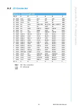
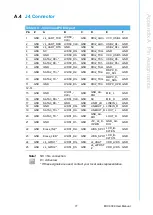
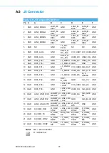
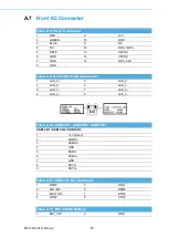
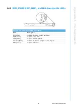
Page 85: ...Appendix A A Pin Assignments This appendix provides the pin assignments...
Page 94: ...MIC 3399 User Manual 82...
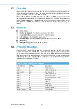
Page 97: ...Appendix C C FPGA Specifications This appendix describes FPGA configuration...
Page 99: ...87 MIC 3399 User Manual Appendix C FPGA Specifications...