


81
MIC-3399 User Manual
Ap
pe
nd
ix A
Pin
A
ss
ign
m
en
ts
A.8
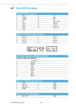
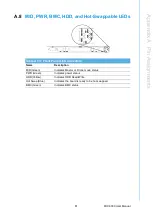
M/D, PWR, BMC, HDD, and Hot-Swappable LEDs
Table A.13: Front Panel LED Indicators
Name
Description
M/D (Green)
Indicates Master or Drone mode status
PWR (Green)
Indicates power status
HDD (Yellow)
Indicates HDD Read/Write
Hot Swap (Blue)
Indicates the board is ready to be hot-swapped.
BMC (Green)
Indicates BMC status
Summary of Contents for MIC-3399
Page 8: ...MIC 3399 User Manual viii...
Page 29: ...Chapter 2 2 AMI BIOS Setup This chapter describes how to configure the AMI BIOS...
Page 47: ...35 MIC 3399 User Manual Chapter 2 AMI BIOS Setup 2 3 3 8 Southbridge Figure 2 19 Southbridge...
Page 63: ...Chapter 3 3 IPMI Configuration This chapter describes IPMI con figuration for MIC 3399...
Page 85: ...Appendix A A Pin Assignments This appendix provides the pin assignments...
Page 94: ...MIC 3399 User Manual 82...
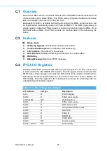
Page 97: ...Appendix C C FPGA Specifications This appendix describes FPGA configuration...
Page 99: ...87 MIC 3399 User Manual Appendix C FPGA Specifications...