background image

Chapter 3  LAN Configuration

2 7

3.3 Installation for Windows NT 4.0

Before installing; create a new folder [

0

], \MIC3389\D_82559\,

in your disk drive, and download all files from the directory,
\MIC3389\D_82559\, on the utility CD-ROM to it.

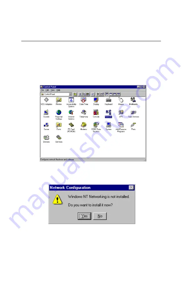
1. In the Windows NT screen, select "Start", click "Settings".
Click the "Control Panel" item and choose "Network".

2. Click "Yes".

Summary of Contents for MIC-3389

Page 1: ...MIC 3389 6U size CompactPCITM Master SBC with Dual Single Pentium III Processors ...

Page 2: ...rChannel FEC is a trademark of Cisco Systems Inc IBM PS 2 OS 2 and VGA are trademarks of International Business Machines Corporation Intel Pentium and PRO 100 are trademarks of Intel Corporation Windows is a registered trademark of Microsoft Corporation NetWare is a trademark of Novell Inc Symbios is a trademark of Symbios Logic Corporation PICMG CompactPCI and the PICMG and CompactPCI logos are t...

Page 3: ...nt materials service time and freight Please consult your dealer for more details If you think you have a defective product follow these steps 1 Collect all the information about the problem encountered For example CPU speed Advantech products used other hardware and software used etc Note anything abnormal and list any on screen messages you get when the problem occurs 2 Call your dealer and desc...

Page 4: ...use cable One bag of screws One warranty certificate This user s manual If any of these items are missing or damaged contact your distributor or sales representative immediately Technical Support and Sales Assistance If you have any technical questions about the MIC 3389 or any other Advantech products please visit our support website at http www advantech com tw support For more information about...

Page 5: ... 5 1 Jumper Locations 7 1 5 2 PVIO Selection JP2 7 1 5 3 Clear CMOS JP3 8 1 5 4 Enable Disable On board Hardware Monitor JP7 JP8 8 1 6 Connectors 9 1 7 Safety Precautions 12 1 8 Installing SDRAM DIMMs 12 1 9 Installing Dual Single CPU Heat Sink and Fans 14 2 Connecting Peripherals 17 2 1IDEDevice 18 2 2 USB Connector CN2 18 2 3 PS 2 Keyboard and Mouse Connector CN5 19 2 4 VGA Display Connector CN6...

Page 6: ...9 Load Optimized Defaults 57 5 10 Set Password 58 5 11 Save Exit Setup 59 5 12 Exit Without Saving 60 A Programming the Watchdog Timer 61 A 1 Programming the Watchdog Timer 62 B Pin Assignments 65 B 2 Keyboard and Mouse Connnector CN2 66 B 1USB Connectors CN1 66 B 3VGA Display Connector CN6 66 B 4 COM1 and COM2 Serial Ports CN7 and CN8 66 B 5 Ethernet RJ 45 Connectors CN11 CN12 68 B 6 System I O P...

Page 7: ...1 Installing the card into the chassis 21 Figure 5 1 Initial Setup screen 50 Figure 5 2 Standard CMOS Features screen 51 Figure 5 3 Advanced BIOS Features screen 52 Figure 5 4 Advanced Chipset Features screen 55 Figure 5 5 Integrated Peripherals screen 55 Figure 5 6 PnP PCI Configurations screen 56 Figure 5 7 PC Health Status screen 56 Figure 5 8 Load Optimized Defaults screen 57 Figure 5 9 Set Pa...

Page 8: ...onnectors 66 Table B 2 MIC 3389 keyboard connector 66 Table B 3 MIC 3389 CRT display connector 66 Table B 4 MIC 3389 COM1 and COM2 serial ports 66 Table B 5 MIC 3389 Ethernet RJ 45 connectors 68 Table B 6 System I O ports 69 Table B 7 DMA channel assignments 69 Table B 8 Interrupt assignments 70 Table B 9 J1 connector pin assignments 71 Table B 10 J2 connector pin assignments 72 Table B 11 J3 conn...

Page 9: ...1 General Information CHAPTER ...

Page 10: ...ith the 100 133 MHz front side bus 64 bit CompactPCITM Interface The MIC 3389 supports a 64 bit PCI interface on the physical CompactPCITM connectors J1 and J2 Through the Intel 21154 PCI to PCI bridge the MIC 3389 is applicable up to 8 slot CompactPCI enclosures can drive up to seven bus master PCI slots On board VGA Dual LAN Dual USB Serial Ports The MIC 3389 offers complete all the functions of...

Page 11: ... slots Compact two slot wide 1 3 Specifications 1 3 1 Standard SBC Functions CPU One Dual Intel Pentium III processors up to 1 GHz BIOS Award 2 Mb flash memory Chipset ServerWorks ServerSet III LE chipset Front Side Bus Clock 133 100 MHz Bus Interface 32 bit 33 MHz 64 bit 66 or 33 MHz 2nd level cache 256 KB on die RAM Two DIMM sockets support up to 2 GB PC 133 Registered SDRAM with ECC Max memory ...

Page 12: ...panel Watchdog timer Can generate a system reset Software enabled disabled Time interval is from 1 to 63 seconds jumperless with run time setup PCI to PCI bridge One Intel r DEC 21154 controller chip drives up to 7 PCI master peripherals 1 3 2 10 100Base TX Ethernet Interface Controller chips Dual Intel 82559 Fast Ethernet controller chips 10 Mbps or 100 Mbps auto switchable Dual LAN ports on the ...

Page 13: ...ower Consumption 5V 10A 3 3V 1 8 mA 12V 240 mA Board size 233 35 x 160 mm 6U size 2 slot 8 TE wide Weight 0 8 Kg 1 8 lb Shock 20 G operating 50 G storage transit Random vibration 1 5 Grms 1 3 5 Certificate CE ClassA FCC ClassA 1 3 6 Standards and Software Compliant with PICMG 2 0 R3 0 CompactPCI and 2 1 Hot Swap specifications Support for Windows 2000 Windows NT Linux Red Hat 7 0 and Solaris 8 1 3...

Page 14: ...ash socket Slot Width RIO 3302 V 2 1 2 V 2 V V 1 RIO 3302S V 2 1 2 V V 2 V V 1 1 3 8 Recommended Rear Transition Boards Note The MIC 3389 does not support SCSI function Note For more information about the rear transition boards please visit our website and download their user s manuals or contact with our local sales representatives ...

Page 15: ...Controller Battery Real Time Clock Watchdog Timer Award Flash BIOS PC 133 Pentium III Processor PC 133 Pentium III Processor ServerWorks ServerSet III LE chipset PCI to PCI bridge Backplane I O KB Mouse Floppy EIDE COM Primary CompactPCI Bus PC 133 Registered SDRAM with ECC up to 2GB 1 4 Functional Block Diagram Figure 1 1 MIC 3389 functional block diagram ...

Page 16: ...e in the function JP2 PVIO selection JP3 Clear CMOS JP7 Enable Disable on board hardware monitor function JP8 Enable Disable external alarm 1 5 2 PVIO Selection JP2 The jumper JP2 is used to select the PCI bus reference voltage before the PCI to PCI bridge PVIO The MIC 3389 allows PVIO to be set to either 5 V or 3 3 V The default is configured as 3 3V If the different voltage is needed please refe...

Page 17: ... The MIC 3389 provides the on board hardware monitor function From the CMOS users can read the MIC 3389 s dual CPU status e g the CPU voltages temperatures and fan speeds the battery voltage and the on board 3 3 V 5 V and 12 V voltages The MIC 3389 default setting is to enable the on board hardware monitor function Should an users wants to disable it and to enable an external alarm system please r...

Page 18: ...connector location Chapter 2 gives instructions for connecting external devices to your MIC 3389 Table 1 5 MIC 3389 connector descriptions Number Function CN1 USB connectors CN2 PS 2 keyboard and mouse connector CN3 and CN5 Connectors for CPU power module 1 CN4 CPU1 fan connector CN6 VGA connector CN7 COM1 CN8 COM2 CN9 and CN10 Connectors for CPU power module 2 CN11 Ethernet connector 2 CN12 Ether...

Page 19: ...Chapter 1 General Information 1 1 Figure 1 2 MIC 3389 jumper and connector locations ...

Page 20: ...1 2 MIC 3389 User s Manual Figure 1 3 MIC 3389 front panel connector and indicator locations ...

Page 21: ...lectrical descharges and fields Keep the card in its antistatic packaging when it is not installed in the PC and place it on a static dessipa tive mat when you are working with it Wear a grounding wrist strap for continuous protection 1 8 Installing SDRAM DIMMs The MIC 3389 provides two 168 pin DIMM sockets for the 3 3V Registered PC 133 SDRAM with ECC The approved SDRAM modules are showed in Appe...

Page 22: ...tor contacts touch The DIMM should not move around in its socket 6 Repeat this operation for the rest of module Note The DIMM modules can only fit into the sockets in one way in accordance with the keyed notchs along the bottom edge of the modules Their gold pins must point down inton the DIMM socket Figure 1 4 SDRAM installation ...

Page 23: ...pliant and the same speed up to 1 GHz In order to meet critical environmental condi tions and the physical space of the MIC 3389 at the same time Advantech designed a heat sink together with two slim fans to fulfill both needs Please refer to Figure 1 5 for an illustration for the installation of the dual CPUs heat sink and dual fans For the installation of one CPU and one CPU terminator please re...

Page 24: ...as to install the both power modules onto the MIC 3389 Note For the single CPU operation on the MIC 3389 it has to install one CPU terminator into the rest CPU socket and do not install the power module beside the CPU terminator Note To have better ventilation we still suggest users to install the both slim fans even if there is only one CPU installed on the MIC 3389 board ...

Page 25: ...2 Connecting Peripherals CHAPTER ...

Page 26: ...s on the top side of a hard disk drive Warning Plug the other end of the cable into the drive with pin 1 on the cable corresponding to pin 1 on the drive Improper connection will damage the drive Note We don t recommend connection to the following Seagate brand IDE HDD models ST 31276A ST 31720A ST 32531A ST 33240A or ST 34340A 2 2 USB Connector CN2 The MIC 3389 provides dual USB Universal Serial ...

Page 27: ...y are detailed in Appendix B 2 5 Serial Ports CN7 and CN8 The MIC 3389 offers two serial ports COM1 and COM2 both in RS 232 These ports allow users to connect to serial devices a mouse printers etc or a communication network You can select the address for each port For example 3F8H COM1 2F8H COM2 or disable it using the BIOS Advanced Setup pro gram covered in Chapter 5 Different devices implement ...

Page 28: ...ndling while plugging and unplugging Improper installation of a card can easily damage the backplane of the chassis The inject eject handles of MIC 3389 help you install and remove the card easily and safely Follow the procedure below to install the MIC 3389 into a chassis To install a card 1 Hold the card vertically Be sure that the card is pointing in the correct direction The components of the ...

Page 29: ...all a card by forcing it into the chassis 5 Pull the upper handle down and lift the lower handle up to push the card into place 6 Secure the card by pushing in the red handle to lock it into place To remove a card 1 Unscrew the screws on the front panel 2 Lift the upper handle up and press the lower handle down to release the card from the backplane 3 Slide the card out Figure 2 1 Installing the c...

Page 30: ...2 2 MIC 3389 User s Manual ...

Page 31: ...3 LAN Configuration CHAPTER ...

Page 32: ...tive Load Balancing ALB creates a team of 2 channels to increase transmission throughput Also includes AFT and ALB This function works with any 100BASE TX switch Fast EtherChannel FEC creates a team of 2 to 4 channels to increase transmission and reception throughput Also includes AFT This function requires a Cisco switch with FEC capability The MIC 3389 comes with drivers for a wide variety of ne...

Page 33: ...SETUP INF Drivers for Windows 3 1 For Novell NetWare MIC3389 D_82559 INFO NETWARE NETWARE TXT Installa tion instructions for Novell NetWare MIC3389 D_82559 NWSERVER 3X4X OLD E100B LAN Drivers for NetWare 3 12 and 4 10 MIC3389 D_82559 NWSERVER 311LAN E100B LAN Drivers for NetWare 3 11 MIC3389 D_82559 OS2 E100BODI SYS Drivers for NetWare OS 2 ODI Client MIC3389 D_82559 DOS E100BODI COM Drivers for D...

Page 34: ...driver MIC3389 D_82559 OS2 E100B OS2 Drivers for general NDIS 2 X OS 2 driver Before installing drivers please refer to the installation instructions of each operating system Note Do not use the driver recommended by the Windows 95 98 NT Add New Hardware wizard Choose the driver from the utility CD ROM disc Note Operating system vendors may post driver updates on their web sites Please visit the w...

Page 35: ...ore installing create a new folder 0 MIC3389 D_82559 in your disk drive and download all files from the directory MIC3389 D_82559 on the utility CD ROM to it 1 In the Windows NT screen select Start click Settings Click the Control Panel item and choose Network 2 Click Yes ...

Page 36: ...2 8 MIC 3389 User s Manual 3 Click Wired to the Network or users may choose Remote access to the network if applicable 4 Click Select from list ...

Page 37: ...Chapter 3 LAN Configuration 2 9 5 Click Have Disk 6 Type in C MIC3389 D_82559 in the blank column and click OK C your hard disk drive ...

Page 38: ...3 0 MIC 3389 User s Manual 7 Click OK 8 Click Next ...

Page 39: ...Chapter 3 LAN Configuration 3 1 9 Click Next 10 Click Next ...

Page 40: ...3 2 MIC 3389 User s Manual 11 Click Next 12 Insert Windows NT source disc in drive E Type E I386 in the blank column or any other directory that contains the Windows NT files Click Continue ...

Page 41: ...Chapter 3 LAN Configuration 3 3 13 Wait for the installation to finish 14 Complete the settings with users network settings Click OK ...

Page 42: ...3 4 MIC 3389 User s Manual 15 Click Next 16 Click Next ...

Page 43: ...Chapter 3 LAN Configuration 3 5 17 Click Yes to restart the computer and enable the changes to take effect ...

Page 44: ...3 6 MIC 3389 User s Manual ...

Page 45: ...C H A P T E R 4 PCI VGA Setup ...

Page 46: ...holds the necessary files for setting up the VGA display under the directory MIC 3389 VGA The contents and path names of this directory are listed below MIC3389 VGA Win9x VGA utility for Windows 95 98 MIC3389 VGA Nt40 VGA utility for Windows 4 0 MIC3389 VGA Win2k VGA utility for Windows 2000 Complete the following steps to install the VGA driver Follow the procedures in the flow chart that apply t...

Page 47: ...Chapter 4 PCI VGA Setup 39 2 Click 6U CPU Boards 4 3 Installation for Windows NT 4 0 1 Insert the utility CD ROM disc in the CD ROM drive and wait for the auto run screen to pop up Click Install Drivers ...

Page 48: ...40 MIC 3389 User s Manual 4 Under VGA Drivers menu click WIN NT 3 Click MIC 3389 ...

Page 49: ...Chapter 4 PCI VGA Setup 41 5 Wait for the system preparation before installation 6 Click Next ...

Page 50: ...42 MIC 3389 User s Manual 7 Click Yes 8 Wait for the system copies files ...

Page 51: ...Chapter 4 PCI VGA Setup 43 9 Wait for installation to finish 10 Click Finish to restart the computer and enable the change to take effect ...

Page 52: ...44 MIC 3389 User s Manual 2 Click 6U CPU Boards 4 4 Installation for Windows 2000 1 Insert the utility CD ROM disc in the CD ROM drive and wait for the auto run screen to pop up Click Install Drivers ...

Page 53: ...Chapter 4 PCI VGA Setup 45 4 Under VGA Drivers menu click WIN 2000 3 Click MIC 3389 ...

Page 54: ...46 MIC 3389 User s Manual 5 Wait for the system preparation before installation 6 Click Next ...

Page 55: ...Chapter 4 PCI VGA Setup 47 7 Click Yes 8 Click Yes ...

Page 56: ...48 MIC 3389 User s Manual 9 Wait for the system copies files 10 Wait for installation to finish 11 Click Finish to restart the computer and enable the change to take effect ...

Page 57: ...C H A P T E R 5 Award BIOS Setup ...

Page 58: ...tup Turn on the computer and check for the patch code If there is a number assigned to the patch code it means that the BIOS supports your CPU If there is no number assigned to the patch code please contact Advantech s application engineer to obtain an up to date patch code file This will ensure that your CPU s system status is valid After ensuring that you have a number assigned to the patch code...

Page 59: ...tandard CMOS Features option from the Initial Setup Menu and the screen below will be displayed This standard setup menu allows users to configure system components such as date time hard disk drive floppy drive display and memory Figure 5 2 Standard CMOS Features screen ...

Page 60: ...ure 5 3 Advanced BIOS Features screen Virus Warning During and after the system boots up any attempt to write to the boot sector or partition table of the hard disk drive will halt the system If this happens a warning message will be displayed You can run the anti virus program to locate the problem If Virus Warning is Disabled no warning message will appear if anything attempts to access the boot...

Page 61: ...ZIP drive HDD 0 Computer will boot from the primary master hard disc drive SCSI Computer will boot from the SCSI drive CD ROM Computer will boot from the CD ROM drive HDD 1 Computer will boot from the primary slave hard disk drive HDD 2 Computer will boot from the secondary master hard disk drive HDD 3 Computer will boot from the secondary slave hard disk drive Disabled Computer will boot from oth...

Page 62: ...em will boot but access to Setup will be denied if the correct password is not entered at the prompt Note To disable security select Set Password in the Initial Setup menu At this point you will be asked to enter a password Simply hit the ENTER key to disable security When security is disabled the system will boot and you can enter Setup freely OS Select for DRAM 64 MB This setting is for use unde...

Page 63: ...Chapter 5 Award BIOS Setup 55 Figure 5 4 Advanced Chipset Features screen 5 6 Integrated Peripherals Figure 5 5 Integrated Peripherals screen ...

Page 64: ...tatus The MIC 3389 supports the on board hardware monitor function From the PC Health Status screen wers can read the values ablut the CPU temperatures CPU FAN speeds CPU voltages Vcore 1 Vcore 2 the battery voltage and the actual voltages for the on board 3 3 V 5 V and 12 V Figure 5 7 PC Health Status screen ...

Page 65: ...apter 5 Award BIOS Setup 57 5 9 Load Optimized Defaults Load Optimized Defaults loads the most appropriate values of the system parameters for maximum performance Figure 5 8 Load Optimized Defaults screen ...

Page 66: ...al Setup menu and press Enter The password can be at most 8 characters long Remember to enable this feature You must first select the Security Option in the Advanced BIOS Features to be either Setup or System Pressing Enter again without typing any characters can disable the password setting function Figure 5 9 Set Password screen ...

Page 67: ...alues entered in the setup utilities will be recorded in the CMOS memory of the chipset The microprocessor will check this every time you turn your system on and compare this to what it finds as it checks the system This record is required for the system to operate Figure 5 10 Save Exit Setup screen ...

Page 68: ... User s Manual 5 12 Exit Without Saving Selecting this option and pressing the Enter key lets you exit the Setup program without recording any new values or changing old ones Figure 5 11 Exit Without Saving screen ...

Page 69: ...Programming the Watchdog Timer A A PPENDIX ...

Page 70: ...chdog timer you must write a program which writes a value to I O port address 443 hex This output value represents time interval The value range is from 01 hex to 3F hex and the related time interval is 1 sec to 63 sec Data TimeInterval 01 1 sec 02 2 sec 03 3 sec 04 4 sec 3F 63 sec ...

Page 71: ...example shows how you might program the watchdog timer in BASIC 10 REM Watchdog timer example program 20 OUT H444 data REM Start and restart the watchdog 30 GOSUB 1000 REM Your application task 1 40 OUT H444 data REM Reset the timer 50 GOSUB 2000 REM Your application task 2 60 OUT H444 data REM Reset the timer 70 X INP H43 REM Disable the watchdog timer 80 END 1000 REM Subroutine 1 your applicatio...

Page 72: ...6 4 MIC 3389 User s Manual ...

Page 73: ...B Pin Assignments APPENDIX ...

Page 74: ...eyboard and Mouse Connnector CN2 Table B 2 MIC 3389 keyboard connector Pin Signal 1 KDAT 2 MDAT 3 GND 4 VCC 5 KCLK 6 MCLK 1 2 3 4 5 6 Table B 1 MIC 3389 USB connectors Pin Signal 1 VCC 2 USBD0 3 USBD0 4 GND B 1 USB Connectors CN1 1 4 ...

Page 75: ...EEN 10 GND 3 BLUE 11 N C 4 N C 12 SDA 5 GND 13 HSYNC 6 GND 14 VSYNC 7 GND 15 SCL 8 GND B 4 COM1 and COM2 Serial Ports CN7 and CN8 Table B 4 MIC 3389 COM1 and COM2 serial ports COM1 COM2 Pin Signal Pin Signal 1 NRLSD1 1 NRLSD2 2 NRX1 2 NRX2 3 NTX1 3 NTX2 4 NDTR1 4 NDTR2 5 GND 5 GND 6 NDSR1 6 NDSR2 7 NRTS1 7 NRTS2 8 NCTS1 8 NCTS2 9 NRI1 9 NRI2 ...

Page 76: ...6 8 MIC 3389 User s Manual B 5 Ethernet RJ 45 Connectors CN11 CN12 Table B 5 MIC 3389 Ethernet RJ 45 connectors Pin Signal 1 TX 2 TX 3 RX 4 N C 5 N C 6 RX 7 N C 8 N C ...

Page 77: ... time clock non maskable interrupt NMI mask 081 091 DMA page register 0A0 0A1 Interrupt controller 2 0C0 0DF DMA controller 0F00F8 0FF Math co processor 1F0 1F7 Fixed disk 2F8 2FF Serial port 2 3B0 3DF VGA 3F0 3F7 Diskette controller 3F8 3FF Serial port 1 B 7 DMA Channel Assignments Table B 7 DMA channel assignments Channel Function 0 Available 1 Available 2 Floppy disk 8 bit transfer 3 Available ...

Page 78: ...troller 2 cascade IRQ 3 Serial communication port 2 IRQ 4 Serial communication port 1 IRQ 5 Available IRQ 6 Diskette controller FDC IRQ 7 Available IRQ 8 Real time clock IRQ 9 Cascaded to INT 0A IRQ 2 IRQ 10 Available IRQ 11 Available IRQ 12 PS 2 mouse IRQ 13 INT from co processor IRQ 14 Fixed disk controller IRQ 15 Fixed disk controller Ethernet function is auto sensing ...

Page 79: ...I O AD11 AD10 19 3 3V AD15 AD14 GND AD13 18 SERR GND 3 3V PAR C BE1 17 3 3V IPMBSCL IPMBSDA GND PERR 16 DEVSEL GND V I O STOP LOCK 15 3 3V FRAME IRDY GND TRDY 12 14 KEY AREA 11 AD18 AD17 AD16 GND C BE2 10 AD21 GND 3 3V AD20 AD19 9 C BE3 GND AD23 GND AD22 8 AD26 GND V I O AD25 AD24 7 AD30 AD29 AD28 GND AD27 6 REQ0 GND 3 3V CLK AD31 5 BRSVP1A5 BRSVP1B5 RST GND GNT0 4 IPMBPWR Healthy V I O INTP INTS ...

Page 80: ...RSVP2B16 DEG GND BRSVP2E16 15 BRSVP2A15 GND FAL REQ5 GNT5 14 AD35 AD34 AD33 GND AD32 13 AD38 GND V I O AD37 AD36 12 AD42 AD41 AD40 GND AD39 11 AD45 GND V I O AD44 AD43 10 AD49 AD48 AD47 GND AD46 9 AD52 GND V I O AD51 AD50 8 AD56 AD55 AD54 GND AD53 7 AD59 GND V I O AD58 AD57 6 AD63 AD62 AD61 GND AD60 5 C BE5 GND V I O C BE4 PAR64 4 V I O BRSVP2B4 C BE7 GND C BE6 3 CLK4 GND GNT3 REQ4 GNT4 2 CKL2 CLK...

Page 81: ...BD7 ICSOB IIORB ICS1B HDRDYB 15 HDBDRQ IDACKB HDBSA2 HDBIRQ IIOWB 14 NRTS1 NDSR1 HDBSA1 GND HDBSA0 13 NRI1 NCTS1 NTX1 NRX1 NRLSD1 12 ID0 ID2 ID4 ID7 NDTR1 11 ID1 ID3 ID8 ID6 ID12 10 ID5 ID9 ID10 ID11 ID13 9 ID15 ID14 HDRQ HCS3 HIOR 8 HIRQ HACK 5V HDA2 HIOW 7 HLED GND HRST1 HRDY HCS1 6 12V 5V GND HDA0 HDA1 5 5V GPIO5 IOCHK SMBCLK SMBDATA 4 KDAT KCLK MDTA MCLK GND 3 DSKCHG MOA STEP HEAD TRAK0 2 DSA ...

Page 82: ...2 21 USB2RX LANRX N C GND COMRTS2 20 N C N C N C N C COMCTS2 19 N C N C N C N C COMTX2 18 N C N C N C N C COMLSD2 17 N C N C N C N C COMDSR2 16 N C N C N C N C COMRI2 15 N C N C N C N C COMRX2 12 14 KEY AREA 11 N C N C N C N C N C 10 N C N C N C N C N C 9 N C N C N C N C N C 8 N C N C N C N C N C 7 N C N C N C N C N C 6 N C N C N C N C N C 5 N C N C N C CRT SCL N C 4 N C N C N C YNC N C 3 N C N C ...

Page 83: ...Memory Approval List C A PPENDIX ...

Page 84: ...G K4S560432A TC75 512 MB PC133 REGISTERED 4 SMART SM572284578E83R 1 GB PC133 REGISTERED 5 ATP AR16V72C4S4GAS SAMSUNG KM44S16030CT G7 128 MB PC133 REGISTERED 6 ATP AR32V72C4S4GAS SAMSUNG K4S280432A TC75 256 MB PC133 REGISTERED 7 ATP AR64V72C4S8GAS SAMSUNG K4S560432A TC75 512 MB PC133 REGISTERED 8 ATP AR128V72C4SSGAS SAMSUNGSEC 12950 37 1 GB PC133 REGISTERED 9 KINGMAX MPIB63S 683 256 MB PC133 REGIST...

Reviews: