6
HMI-640S User's Manual
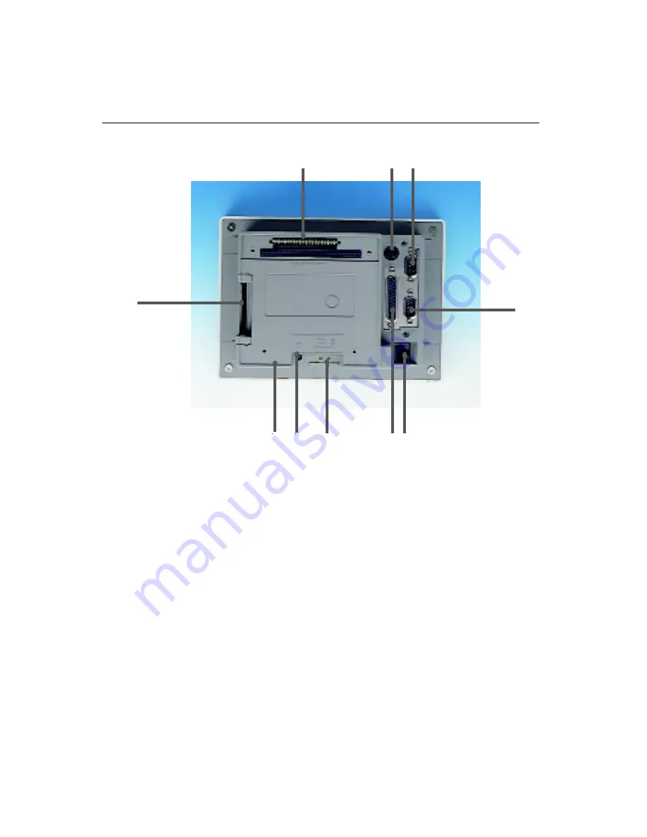
1.4 I/O Arrangement
The I/O arrangement of the HMI-640S is shown below:
Note:
Serial port COM2 can be configured to operate in
RS-232, RS-422 or RS-485 mode. This is set by DIP
switches on the upper side of the back cover. Before
attaching connectors, please make sure the DIP
switch settings are correct. (See Appendix B for
COM2 port settings.)
a. IDE connector
b. PC/104 slot
c. PS/2 keyboard and
mouse connector
d. Serial COM2 port
e. Serial COM1 port
f. Ethernet port
g. Parallel port
h. 24 V
DC
input connector
& chassis GND
i. LCD contrast
j. Slide power switch
a
d
e
i h g f
b
c
j
Summary of Contents for HMI-640S
Page 1: ...HMI 640S 486 based panel PC with 6 0 LCD flat panel display User s Manual...
Page 10: ......
Page 20: ...10 HMI 640S User s Manual...
Page 43: ...Chapter 4 CPC 2245N Main Borad 33 4 3 Board layout dimensions...
Page 66: ...56 HMI 640S User s Manual 4 12 Card installation...
Page 67: ...Chapter 4 CPC 2245N Main Borad 57 4 13 Card removal...
Page 68: ...58 HMI 640S User s Manual 4 14 FPC cable installation...
Page 72: ...62 HMI 640S User s Manual 5 3 Board layout dimensions...
Page 74: ...64 HMI 640S User s Manual 5 5 Board layout jumper connector locations...
Page 81: ...Chapter 5 CPC 2520 VGA LCD Control Board 71 5 12 FPC cable installation...
Page 82: ...72 HMI 640S User s Manual...
Page 88: ...78 HMI 640S User s Manual...
Page 92: ...82 HMI 640S User s Manual...


