


EKI-7712G-4FMPI User Manual
90
Entry List
To access this page, click
Security
>
Access Control List
>
IP ACL
>
Entry List
.
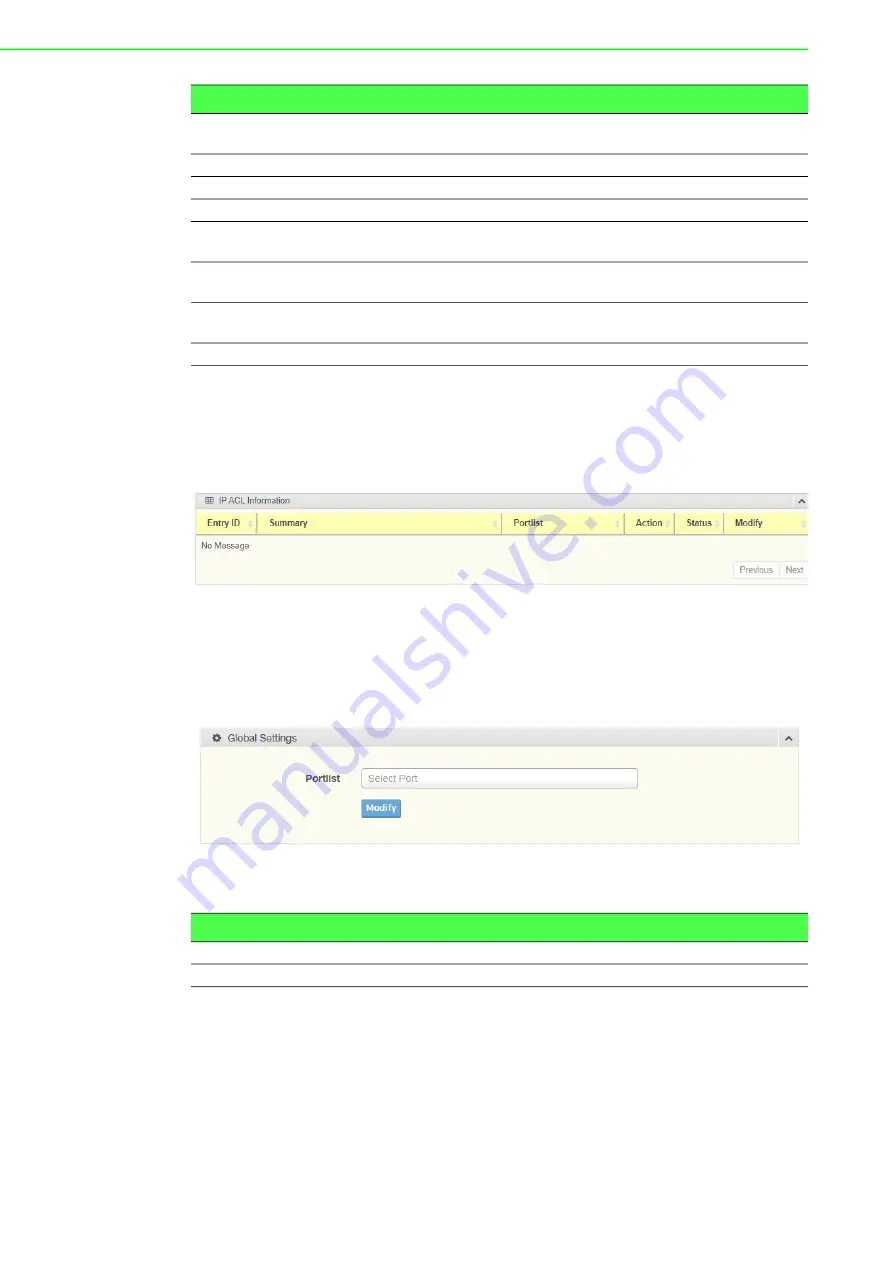
The ensuing table for
IP ACL Information
settings are informational only: Entry ID,
Summary, Portlist, Action, Status and Modify (Click
Edit
to edit the desire entry id or
Delete
to delete the desired entry id).
Figure 4.97 Security
>
Access Control List
>
IP ACL
>
Entry List
.
4.7.10
IP Source Guard
4.7.10.1
Global Settings
To access this page, click
Security
>
IP Source Guard
>
Global Settings
.
Figure 4.98 Security > IP Source Guard > Global Settings
The following table describes the items in the previous figure.
The ensuing table for
Global Information
settings are informational only: Verify
Ports.
IP Protocol
Click the drop down menu to select the IP protocol. Options include:
none, ICMP, TCP or UDP.
L4 Destination Port
Enter a value to specify the L4 destination port.
L4 Source Port
Enter a value to specify the L4 source port.
Portlist
Select the port to configure for the IP ACL function.
Action
Click the drop down menu to select the IP ACL action. Options
include: Permit, Drop or Assign Queue.
Assign Queue
Click the drop down menu to select the queue. The function is only
available when
Action
is
Assign Queue
.
Status
Click the drop down menu to select the IP ACL status. Options
include: Active or Inactive.
Add
Click
Add
to add an IP ACL entry.
Item
Description
Item
Description
Portlist
Select the port to verify.
Modify
Click
Modify
to save the values and update the screen.
Summary of Contents for EKI-7712G-4FMPI
Page 1: ...User Manual EKI 7712G 4FMPI 8GE 4G SFP Port Managed Redundant High PoE Industrial Switch ...
Page 15: ...Chapter 1 1Product Overview ...
Page 21: ...Chapter 2 2Switch Installation ...
Page 36: ...Chapter 3 3Configuration Utility ...
Page 42: ...Chapter 4 4Managing Switch ...
Page 167: ...Chapter 5 5Troubleshooting ...