background image

EKI-7428 Series User Manual

48

4.5.4.4

Port-VLAN Mapping

To access this page, click 

L2 Switching

 > 

802.1Q VLAN

 > 

Port-VLAN Mapping

.

The ensuing table for 

Port-VLAN Mapping Table

 settings are informational only:

Port, Mode, Administrative VLANs and Operational VLANs.

4.5.5

Q-in-Q

Q-in-Q is commonly referred as VLAN stacking in which VLANs are nested by adding
two tags to each frame instead of one. Network service provider and users both can
use VLANs and makes it possible to have more than the 4094 separate VLANs
allowed by 802.1Q.

There are three ways in which a machine can be connected to a network carrying
double-tagged 802.1ad traffic:

via a untagged port, where both inner and outer VLANs are handled by the 
switch or switches (so the attached machine sees ordinary Ethernet frames);

via a single-tagged (tunnel) port, where the outer VLAN only is handled by the 
switch (so the attached machine sees single-tagged 802.1Q VLAN frames); or

via a double-tagged (trunk) port, where both inner and outer VLANs are handled 
by the attached machine (which sees double-tagged 802.1ad VLAN frames).

4.5.5.1

Global Settings

The Global Settings page allows you to set the outer VLAN Ethertype setting.

To access this page, click 

L2 Switching

 > 

Q-in-Q

 > 

Global Settings

.

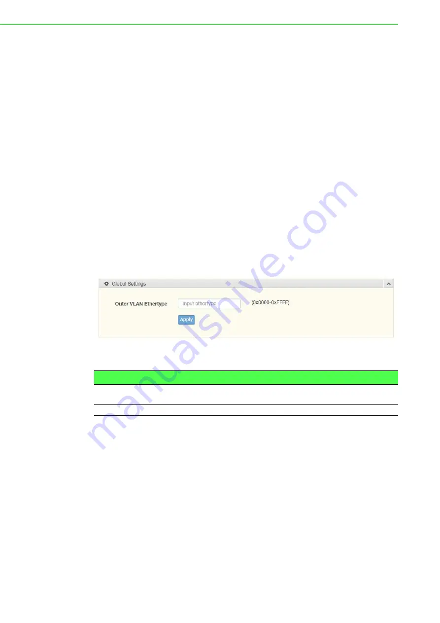
Figure 4.25 L2 Switching > Q-in-Q > Global Settings

The following table describes the items in the previous figure.

The ensuing table for 

QinQ Global Information

 settings are informational only:

Outer VLAN Ethertype.

Item

Description

Outer VLAN 
Ethertype

Enter the outer VLAN handled by the switch giving the attached 
machine a single-tagged 802.1Q VLAN frame.

Apply

Click 

Apply

 to save the values and update the screen.

Summary of Contents for EKI-7428 Series

Page 1: ...User Manual EKI 7428 Series 24GE 4G Combo 24GE PoE 4G Combo Port L2 Managed Switch ...

Page 2: ...lation Advantech assumes no liability under the terms of this warranty as a consequence of such events Because of Advantech s high quality control standards and rigorous testing most of our customers never need to use our repair service If an Advantech product is defective it will be repaired or replaced at no charge during the warranty period For out of warranty repairs you will be billed accordi...

Page 3: ...and can radiate radio frequency energy and if not installed and used in accordance with the instruction manual may cause harmful interference to radio communications Operation of this equipment in a residential area is likely to cause harmful interference in which case the user will be required to correct the interference at his own expense Technical Support and Assistance 1 Visit the Advantech we...

Page 4: ...ler immediately 1 x L2 Managed Switch 1 x DIN Rail mounting Bracket and Screws 1 x Wall mounting Bracket Warning Warnings indicate conditions which if not observed can cause personal injury Caution Cautions are included to help you avoid damaging hardware or losing data e g There is a danger of a new battery exploding if it is incorrectly installed Do not attempt to recharge force open or heat the...

Page 5: ...t used for a long time disconnect it from the power source to avoid damage by transient overvoltage Never pour any liquid into an opening This may cause fire or electrical shock Never open the equipment For safety reasons the equipment should be opened only by qualified service personnel If one of the following situations arises get the equipment checked by service personnel The power cord or plug...

Page 6: ...ren Zeitraum nicht benutzt sollten Sie es vom Stromnetz trennen Somit wird im Falle einer Überspannung eine Beschädigung vermieden Durch die Lüftungsöffnungen dürfen niemals Gegenstände oder Flüssigkeiten in das Gerät gelangen Dies könnte einen Brand bzw elektrischen Schlag auslösen Öffnen Sie niemals das Gerät Das Gerät darf aus Gründen der elektrischen Sicherheit nur von authorisiertem Servicepe...

Page 7: ...n period The following guidelines are also recommended Wear a grounded wrist or ankle strap and use gloves to prevent direct contact to the device before servicing the device Avoid nylon gloves or work clothes which tend to build up a charge Always disconnect the power from the device before servicing it Before plugging a cable into any port discharge the voltage stored on the cable by touching th...

Page 8: ...8 Connecting the Switch to Console Port 16 2 9 Power Supply Installation 17 2 9 1 Overview 17 2 9 2 Considerations 18 2 9 3 Grounding the Device 18 2 9 4 Wiring a Relay Contact 19 2 9 5 Wiring the Power Inputs 20 2 10 Reset Button 21 Chapter 3 Configuration Utility 22 3 1 First Time Setup 23 3 1 1 Overview 23 3 1 2 Introduction 23 3 1 3 Administrative Interface Access 23 3 2 Command Line Interface...

Page 9: ...ection 66 4 5 14 CFM 67 4 5 15 ERPS 68 4 6 MAC Address Table 70 4 6 1 Static MAC 70 4 6 2 MAC Aging Time 70 4 6 3 Dynamic Forwarding Table 71 4 7 Security 72 4 7 1 Storm Control 72 4 7 2 Port Security 74 4 7 3 Protected Ports 74 4 7 4 DoS Prevention 75 4 7 5 Applications 77 4 7 6 802 1x 79 4 7 7 IP Security 80 4 7 8 Access Control List 82 4 7 9 IP Source Guard 84 4 7 10 DHCP Snooping 85 4 7 11 ARP...

Page 10: ...x EKI 7428 Series User Manual 4 10 4 System Log 116 4 10 5 DDM 118 4 11 Tools 119 4 12 Modbus TCP Mapping 124 Chapter 5 Troubleshooting 143 5 1 Troubleshooting 144 ...

Page 11: ...gure 4 6 Monitoring Port Monitoring Port Utilization 33 Figure 4 7 Monitoring LLDP Statistics 33 Figure 4 8 Monitoring IGMP Statistics 34 Figure 4 9 System IP Settings 35 Figure 4 10 System DHCP Client Option 82 36 Figure 4 11 System DHCP Auto Provision 37 Figure 4 12 System IPv6 Settings 37 Figure 4 13 System Management VLAN 38 Figure 4 14 System System Time 38 Figure 4 15 L2 Switching Port Confi...

Page 12: ...itching CFM ME Settings 68 Figure 4 59 L2 Switching ERPS ERPS Settings 68 Figure 4 60 L2 Switching ERPS ERPS Groups 69 Figure 4 61 MAC Address Table Static MAC 70 Figure 4 62 MAC Address Table MAC Aging Time 70 Figure 4 63 MAC Address Table Dynamic Forwarding Table 71 Figure 4 64 Security Storm Control Global Settings 72 Figure 4 65 Security Storm Control Port Settings 73 Figure 4 66 Security Port...

Page 13: ...DHCP Server Status Settings 103 Figure 4 112 Management DHCP Server Global Settings 104 Figure 4 113 Management DHCP Server Port Settings 105 Figure 4 114 Management DHCP Server Option 82 Settings 106 Figure 4 115 Management DHCP Server Client MAC Settings 107 Figure 4 116 Management SMTP Client Global Settings 108 Figure 4 117 Management SMTP Client Profile Settings Profile Settings 108 Figure 4 ...

Page 14: ...Chapter 1 1Product Overview ...

Page 15: ...emperature 40 C 70 C 40 F 158 F Storage Temperature 40 C 85 C 40 F 185 F Ambient Relative Humidity 10 95 non condensing Switch Properties MAC Address 8K entry Switching Bandwidth 56 Gbps Power Power Consumption EKI 7428G 4CI 20W 24V EKI 7428G 4CPI 20W 48V Power Input EKI 7428G 4CI 12V 48VDC EKI 7428G 4CPI 48VDC 46 57 VDC for PoE system 53 57 VDC is recommended for PoE devices Certifications Safety...

Page 16: ...ton allows for system soft reset 3 sec or factory default reset 5 sec 2 System LED panel See System LED Panel on page 4 for further details 3 ETH port RJ45 ports x 4 4 SFP LEDs SFP link activity LEDs 5 ETH port Fiber ports x 4 6 PoE LED Link activity LED 7 LNK ACT LED Green 1000M Orange 10 100M 8 ETH port RJ45 ports x 24 EKI 7428G 4CI R M LINK ACT LINK ACT Speed LINK ACT Speed 28 27 26 25 28 27 26...

Page 17: ... A ring port within the ring loop is identified has having a ring ID within a second ring loop Off No ring ports having a ring ID within a secondary ring loop are detected 8 Temp Solid red IC sensor detects a temperature range exceeding set temperature range Off IC sensor detects normal operating temperature SFP 9 SFP LED Solid green SFP or GBIC plug in and link up Blink green Packet transmit and ...

Page 18: ...it occurs upon detecting a power failure A close circuit denotes normal power activity 4 Power block Connect cabling for power wiring No Item Description 1 Ground terminal Screw terminal used to ground chassis 2 Console serial port Console cable port to COM port DB9 male on computer to RS232 managed switch RJ45 female 3 P Fail block An open circuit occurs upon detecting a power failure A close cir...

Page 19: ...EKI 7428 Series User Manual 6 1 3 Dimensions Figure 1 6 EKI 7428G 4CI Dimensions Figure 1 7 EKI 7428G 4CPI Dimensions EKI 7428G 4CI 438 22 41 426 12 EKI 7428G 4CPI 438 22 41 426 12 ...

Page 20: ...Chapter 2 2Switch Installation ...

Page 21: ...m or connect or disconnect cables during periods of lightning activity Caution Before performing any of the following procedures disconnect the power source from the DC circuit Caution Read the installation instructions before connecting the system to its power source Caution The device must be grounded Never defeat the ground conductor or operate the equipment in the absence of a suitably install...

Page 22: ... a hazardous location ensure that the DC power source is located away from the vicinity of the switch Caution The installation of the equipment must comply with all national and local electrical codes Caution Explosion Hazard The area must be known to be nonhazardous before servicing or replacing any components Warning Airflow around the switch must be unrestricted To prevent the switch from overh...

Page 23: ...in a Pollution Degree 2 industrial environment in overvoltage Category II applications as defined in IEC publication 60664 1 at altitudes up to 9842 ft 3 km without derating This equipment is considered Group 1 Class A industrial equipment according to IEC CISPR Publication 11 Without appropriate precautions there may be potential difficulties ensuring electromagnetic compatibility in other enviro...

Page 24: ...ch is now ready for installation on its final location 2 5 Installing the Switch 2 5 1 Rack Mounting 1 Align the rack mount brackets with the holes on the switch 2 Secure the rack mount brackets with the provided screws Figure 2 1 Installing the Rack Mount Brackets 3 Align the switch with the posts on the rack cabinet 4 Secure the switch with the provided screws Figure 2 2 Installing the Switch EK...

Page 25: ...rom device II to device I for full duplex transmission Remember to connect the Tx transmit port of device I to the Rx receive port of device II and the Rx receive port of device I to the Tx transmit port of device II If you make your own cable we suggest labeling the two sides of the same line with the same letter A to A and B to B or A1 to A2 and B1 to B2 2 6 1 Installing SFP Modules To connect t...

Page 26: ...igure 2 5 Attaching a Fiber Optic Cable to a Transceiver 8 Repeat the previous procedures to install any additional SFP transceivers in the switch The fiber port is now setup Note If you are attaching fiber optic cables to the transceiver continue with the following step Otherwise repeat the previous steps to install the remaining SFP transceivers in the device Note Do not remove the dust plug fro...

Page 27: ...ic cable 2 Pull the optic cable out to release it from the transceiver Figure 2 6 Removing a Fiber Optic Cable to a Transceiver 3 Hold the handle on the transceiver and pull the transceiver out of the slot Figure 2 7 Removing an SFP Transceiver Note Replace the dust plug on the slot if you are not installing a transceiver The dust plug protects hardware from dust contamination Handle ...

Page 28: ... RJ45 Ethernet ports are metallic and connected to the GND terminal For best performance use shielded cabling Shielded cabling may be used to provide further protection Figure 2 8 Ethernet Plug Connector Pin Position Maximum cable length 100 meters 328 ft for 10 100 1000BaseT Straight thru Cable Wiring Cross over Cable Wiring Pin 1 Pin 1 Pin 1 Pin 3 Pin 2 Pin 2 Pin 2 Pin 6 Pin 3 Pin 3 Pin 3 Pin 1 ...

Page 29: ... s RJ45 RJ45 port a wired connection for management can be established Figure 2 9 Serial Console Cable Figure 2 10 DB 9 Pin Position Figure 2 11 Pin Assignment DB9 Connector RJ45 Connector NC 1 Orange White NC 2 Orange 2 3 Green White NC 4 Blue 5 5 Blue White 3 6 Green NC 7 Brown White NC 8 Brown To terminal or PC To console port 5 9 1 6 3 6 8 1 7 2 5 4 TXD RJ45 Male RXD NC NC NC NC GND GND 2 3 7 ...

Page 30: ... secondary power supply unit to reduce network down time as a result of power loss Dual power inputs are supported and allow you to connect a backup power source Figure 2 12 Power Wiring for EKI 7428 Series Warning Power down and disconnect the power cord before servicing or wiring the switch Caution Do not disconnect modules or cabling unless the power is first switched off The device only suppor...

Page 31: ...ces for more effective management and servicing 2 9 3 Grounding the Device Note Routing communications and power wiring through the same conduit may cause signal interference To avoid interference and signal degradation route power and communications wires through separate conduits Caution Do not disconnect modules or cabling unless the power is first switched off The device only supports the volt...

Page 32: ...owing section details the wiring of the relay output The terminal block on the EKI 7428 Series is wired and then installed onto the terminal receptor located on the EKI 7428 Series Figure 2 14 Terminal Receptor Relay Contact The terminal receptor includes a total of six pins two for PWR1 two for PWR2 and two for a fault circuit Note Before applying power to the grounded switch it is advisable to u...

Page 33: ...tive positive DC wires into the V V terminals of PW1 If setting up power redundancy connect PW2 in the same manner 3 Tighten the wire clamp screws to secure the DC wires in place Figure 2 16 Installing DC Wires in a Terminal Block Caution Do not disconnect modules or cabling unless the power is first switched off The device only supports the voltage outlined in the type plate Do not use any other ...

Page 34: ...al 2 10 Reset Button Reset configuration to factory default Press and hold Reset button for 5 seconds System reboot Press and hold Reset button for 3 seconds Note Do NOT power off the Ethernet switch when loading default settings ...

Page 35: ...Chapter 3 3Configuration Utility ...

Page 36: ...f explanation of how RSTP works is given in the Spanning Tree section The switch is capable of communicating with other SNMP capable devices on the network to exchange management information This statistical derived information from the network is saved in the Management Information Base MIB of the switch The MIB is divided into several different information storage groups These groups will be ela...

Page 37: ...ch for network access select Add Menu Address Here to reach the System Settings menu The settings in this menu control the switch s general network configuration DHCP Enabled Disabled The switch can automatically obtain an IP address from a server using the Dynamic Host Configuration Protocol DHCP This can speed up initial set up as the network administrator does not have to find an open IP addres...

Page 38: ...th is selected Choose to enable auto negotiation or use fixed settings 100Mbps Fiber ports are Fixed speed only Speed Duplex Flow Control The managed switch accepts three local area network Ethernet Standards The first standard 10BASE T runs 10Mbps with twisted pair Ethernet cable between network interfaces The second local area network standard is 100BASE T which runs at 100Mbps over the same twi...

Page 39: ... subnet mask and default gateway value is the new value of the parameter If value is omitted the current value is displayed Please note that new values will not take effect until explicitly committed Sections and parameter names are case sensitive e g Network is not the same as network 3 2 2 Accessing the CLI To access the CLI interface establish Ethernet or serial connectivity to the switch To co...

Page 40: ...etwork A PC also connected to the network is required to connect to the switch and access the interface through a web browser The required networking information is provided as follows IP address 192 168 1 1 Subnet mask 255 255 255 0 Default gateway 192 168 1 254 User name admin Password admin 3 3 2 System Login Once the switch is installed and connected power on the switch The following informati...

Page 41: ...Chapter 4 4Managing Switch ...

Page 42: ...n 4 2 Recommended Practices One of the easiest things to do to help increase the security posture of the network infrastructure is to implement a policy and standard for secure management This practice is an easy way to maintain a healthy and secure network After you have performed the basic configurations on your switches the following is a recommendation which is considered best practice policy ...

Page 43: ...nformation such as System Name System Location MAC Address Firmware version and more pertaining to the system The information is for review only To modify the device information see the respective item within the user interface To access this page click Monitoring Device Information Figure 4 3 Monitoring Device Information The following table describes the items in the previous figure Item Descrip...

Page 44: ...te of the switch Firmware Version Displays the current firmware version of the switch Firmware Date Displays the current firmware build date of the switch System Object ID Displays the base object ID of the switch System Up Time Displays the time since the last switch reboot Item Description Item Description Target Click the drop down menu to select a target to store the log messages Buffered Stor...

Page 45: ...only dot3StatsAlignmentErrors dot3StatsFCSErrors dot3StatsSingleCollisionFrames dot3StatsMultipleCollisionFrames dot3StatsDeferredTransmissions dot3StatsLateCollisions dot3StatsExcessiveCollisions dot3StatsFrameTooLongs dot3StatsSymbolErrors dot3ControlInUnknownOpcodes dot3InPauseFrames and dot3OutPauseFrames The ensuing table for Rmon MIB Counters settings are informational only etherStatsDropEve...

Page 46: ...informational only LAG Port PartnerSysId PnKey AtKey Sel Mux Receiv PrdTx AtState and PnState 4 3 5 LLDP Statistics The LLDP Statistics page displays the LLDP statistics To access this page click Monitoring LLDP Statistics Figure 4 7 Monitoring LLDP Statistics The following table describes the items in the previous figure The ensuing table for LLDP Global Statistics settings are informational only...

Page 47: ...ics Figure 4 8 Monitoring IGMP Statistics The following table describes the items in the previous figure The ensuing table for IGMP Statistics settings are informational only Total RX Valid RX Invalid RX Other RX Leave RX Report RX General Query RX Special Group Query RX Special Group Source Query RX Leave TX Report TX General Query TX Special Group Query TX and Special Group Source Query TX Item ...

Page 48: ...c DNS Server 1 and Static DNS Server 2 Item Description Mode Click the radio button to select the IP Address Setting mode Static or DHCP IP Address Enter a value to specify the IP address of the interface The default is 192 168 1 1 Subnet Mask Enter a value to specify the IP subnet mask for the interface The default is 255 255 255 0 Gateway Enter a value to specify the default gateway for the inte...

Page 49: ...cuit ID Hex Circuit ID User Define Remote ID Format Remote ID String Remote ID Hex and Remote ID User Define Item Description Mode Click the radio button to enable or disable the DHCP Client Option 82 mode Circuit ID Format Click the drop down menu to set the ID format String Hex User Definition Circuit ID String Enter the string ID of the corresponding class Circuit ID Hex Enter the hex string of...

Page 50: ...k System IPv6 Settings Figure 4 12 System IPv6 Settings The following table describes the items in the previous figure The ensuing table for IPv6 Information settings are informational only Auto Configuration IPv6 In Use Address IPv6 In Use Router IPv6 Static Address IPv6 Static Router and DHCPv6 Client Item Description Status Select the radio button to enable or disable the DHCP Auto Provisioning...

Page 51: ...re 4 13 System Management VLAN The following table describes the items in the previous figure The ensuing table for Management VLAN State are informational only Management VLAN 4 4 6 System Time To access this page click System System Time Figure 4 14 System System Time Item Description Management VLAN Click the drop down menu to select a defined VLAN Apply Click Apply to save the values and updat...

Page 52: ...r the port on the server to which SNTP requests are to be sent Allowed range is 1 to 65535 default 123 Manual Time Click the drop down menus to set local date and time of the system Time Zone Click the drop down menu to select a system time zone Daylight Saving Time Click the drop down menu to enable or disable the daylight saving time settings Daylight Saving Time Offset Enter the offsetting vari...

Page 53: ...dio button to enable or disable the Port Setting function Speed Click the drop down menu to select the port speed Auto Auto 10M Auto 100M Auto 1000M Auto 10 100M 10M 100M or 1000M Duplex Click the drop down menu to select the duplex setting Auto Half or Full Flow Control Click the radio button to enable or disable the flow control function Fiber Port Click the drop down menu to select the port for...

Page 54: ...e The ensuing table for Mirror Status settings are informational only Session ID Destination Port Ingress State Source TX Port and Source RX Port Item Description Session ID Click the drop down menu to select a port mirroring session from the list The number of sessions allowed is platform specific Monitor session state Click the drop down menu to enable or disable the session mode for a selected ...

Page 55: ...5 3 2 LAG Management Link aggregation is also known as trunking It is a feature available on the Ethernet gateway and is used with Layer 2 Bridging Link aggregation allows for the logical merging of multiple ports into a single link To access this page click L2 Switching Link Aggregation LAG Management Figure 4 18 L2 Switching Link Aggregation LAG Management The following table describes the items...

Page 56: ...peed Duplex FlowCtrl Config and FlowCtrl Status 4 5 3 4 LACP Priority Settings The LACP Priority Settings page allows you to configure the system priority for LACP To access this page click L2 Switching Link Aggregation LACP Priority Settings Figure 4 20 L2 Switching Link Aggregation LACP Priority Settings The following table describes the items in the previous figure Item Description LAG Select C...

Page 57: ...ble describes the items in the previous figure The ensuing table for LACP Port Information settings are informational only Port Name Priority Timeout and Mode Item Description Port Select Select a port for the LACP Port Settings The listed available settings are GE1 GE28 However the available settings are dependent on the connected LACP device and may not be listed as displayed in the current figu...

Page 58: ...LAN Management Figure 4 22 L2 Switching 802 1Q VLAN VLAN Management The following table describes the items in the previous figure The ensuing table for VLAN Table settings are informational only VLAN ID VLAN Name VLAN Type and Edit click to enter VLAN name 4 5 4 2 PVID Settings The PVID Settings page allows you to designate a PVID for a selected port define the accepted type and enable disable th...

Page 59: ...ed Type Click the radio button to specify which frames to forward Tag Only discards any untagged or priority tagged frames Untag Only discards any tagged frames All accepts all untagged and tagged frames Whichever you select VLAN tagged frames are forwarded in accordance with the IEEE 802 1Q VLAN standard The default is All Ingress Filtering Click the radio button to specify how you want the port ...

Page 60: ...wing table describes the items in the previous figure Item Description Port Displays the assigned port to the entry Interface VLAN Mode Displays the assigned mode to the listed VLAN port Hybrid Port hybrid model Access Port hybrid model Trunk Port hybrid model Tunnel Port hybrid model Membership Displays the assigned membership status of the port entry options include Forbidden Excluded Tagged or ...

Page 61: ...es so the attached machine sees ordinary Ethernet frames via a single tagged tunnel port where the outer VLAN only is handled by the switch so the attached machine sees single tagged 802 1Q VLAN frames or via a double tagged trunk port where both inner and outer VLANs are handled by the attached machine which sees double tagged 802 1ad VLAN frames 4 5 5 1 Global Settings The Global Settings page a...

Page 62: ...registration and de registration of attributes network identifiers or addresses by end stations and switches with each other Item Description Port Select Enter the switch port part of VLAN configuration to configure the selection as a tunnel port Outer PVID Enter the Port VLAN ID PVID to assigned the native VLAN ID All untagged traffic coming in or out of the 802 1Q port is forwarded based on the ...

Page 63: ...er a number between 6 and 600 An instance of this timer exists for each GARP participant for each port Leave Time Enter a value to specify the time to wait after receiving an unregister request for a VLAN or multicast group before deleting the associated entry in centiseconds This allows time for another station to assert registration for the same attribute in order to maintain uninterrupted servi...

Page 64: ...elligent functionality Traffic detection Energy Efficient Ethernet EEE compliance Inactive link detection Inactive link detection function automatically reduces power usage when inactive links or devices are detected To access this page click L2 Switching 802 3az EEE Figure 4 30 L2 Switching 802 3az EEE The following table describes the items in the previous figure Item Description Status Click to...

Page 65: ...EKI 7428 Series User Manual 52 The ensuing table for EEE Enable Status settings are informational only Port and EEE State ...

Page 66: ...8 2 IGMP Snooping IGMP Snooping is defined as the process of listening to Internet Group Management Protocol IGMP network traffic IGMP Snooping allows a network switch to listen in on the IGMP conversation between hosts and routers and maintain a map of which links need which IP multicast streams Multicasts can be filtered from the links which do not need them in turn controlling which ports recei...

Page 67: ... IGMP Snooping IGMP Querier Figure 4 33 L2 Switching Multicast IGMP Snooping IGMP Querier The following table describes the items in the previous figure The ensuing table for IGMP Querier Status settings are informational only VLAN ID Querier State Querier Status Querier Version and Querier IP IGMP Static Groups To access this page click L2 Switching Multicast IGMP Snooping IGMP Static Groups Figu...

Page 68: ...out periodic general MLD queries and are forwarded through all ports in the VLAN MLD Settings To access this page click L2 Switching Multicast MLD Snooping MLD Settings Figure 4 35 L2 Switching Multicast MLD Snooping MLD Settings The following table describes the items in the previous figure The ensuing table for MLD Snooping Information settings are informational only MLD Snooping State MLD Snoop...

Page 69: ...Status settings are informational only VLAN ID Querier State Querier Status Querier Version and Querier IP MLD Static Group The MLD Static Group page allows you to configure specified ports as static member ports To access this page click L2 Switching Multicast MLD Snooping MLD Static Group Figure 4 37 L2 Switching Multicast MLD Snooping MLD Static Group The following table describes the items in ...

Page 70: ...VLAN ID Port and Expiry Time Sec 4 5 9 Jumbo Frame Jumbo frames are frames larger than the standard Ethernet frame size of 1518 bytes The Jumbo Frame function allows the configuration of Ethernet frame size To access this page click L2 Switching Jumbo Frame Figure 4 38 L2 Switching Jumbo Frame The following table describes the items in the previous figure The ensuing table for Jumbo Frame Config s...

Page 71: ... Tree STP Global Settings The following table describes the items in the previous figure The ensuing table for STP Information settings are informational only STP BPDU Forward PathCost Method and Force Version Item Description Enabled Click the radio button to enable or disable the STP status BPDU Forward Select flooding or filtering to designate the type of BPDU packet PathCost Method Select shor...

Page 72: ... apply to this setting Admin Enable Select Enabled or Disabled to setup the admin profile for the STP port Path Cost 0 Auto Set the port s cost contribution For a root port the root path cost for the bridge 0 means Auto Edge Port Click the drop down menu to set the edge port configuration No Force to false state as link to a bridge Yes Force to true state as link to a host P2P MAC Click the drop d...

Page 73: ...ge Root Path Cost Designated Bridge Root Port and Last Topology Change 4 5 10 4 STP Port Advanced Settings The STP Port Advanced Settings page allows you to select the port list to apply this setting To access this page click L2 Switching Spanning Tree STP Port Advanced Settings Figure 4 42 L2 Switching Spanning Tree STP Port Advanced Settings Item Description Priority Click the drop down menu to ...

Page 74: ...igure The ensuing table for MST Configuration Identification Information settings are informational only Configuration Name and Revision Level 4 5 10 6 MST Instance ID Settings The MST Instance ID Settings page allows you to edit the MSTI ID and VID List settings To access this page click L2 Switching Spanning Tree MST Instance ID Settings Figure 4 44 L2 Switching Spanning Tree MST Instance ID Set...

Page 75: ...s are informational only Bridge Identifier Designated Root Bridge Root Path Cost Designated Bridge Root Port and TCNLast Topology Change The ensuing table for STP Port Status settings are informational only Port Identifier Priority Port Id Path Cost Conf Oper Designated Root Bridge Root Path Cost Designated Bridge Edge Port Conf Oper P2P MAC Conf Oper Port Role and Port State 4 5 10 9 STP Statisti...

Page 76: ...ups page allows you to select the function and role for each device and the connected ports To access this page click L2 Switching X Ring Elite X Ring Elite Groups Figure 4 47 L2 Switching X Ring Elite X Ring Elite Groups The following table describes the items in the previous figure The ensuing table for Information settings are informational only Ring ID Role Port 1 Port 2 and Delete click to de...

Page 77: ...e informational only X Ring Pro State 4 5 12 2 X Ring Pro Groups The X Ring Pro Groups page allows you to select the function and role for each ring ID and its connected ports To access this page click L2 Switching X Ring Pro X Ring Pro Groups Figure 4 49 L2 Switching X Ring Pro X Ring Pro Groups X Ring Pro Groups Settings The following table describes the items in the previous figure Item Descrip...

Page 78: ... role Head Port Click the drop down menu to define the port designation Member Port Click the drop down menu to define the port designation Add Click Add to save the values and update the screen Item Description Couple Ring ID Enter a number to specifies a ranging from 1 to 255 to identify a given X Ring group Port Enter the port to assign to define the couple setting Master Ring ID Click the drop...

Page 79: ...select the interval at which frames are transmitted and the delay before recovery To access this page click L2 Switching Loopback Detection Global Settings Figure 4 54 L2 Switching Loopback Detection Global Settings The following table describes the items in the previous figure Item Description RPair Ring ID Enter a number to specifies a ranging from 1 to 255 to identify a rpair ring ID Port Enter...

Page 80: ...ble for Loopback Detection Port Information settings are informational only Port Enable State and Loop Status 4 5 14 CFM 4 5 14 1 CFM Settings To access this page click L2 Switching CFM CFM Settings Figure 4 56 L2 Switching CFM CFM Settings The following table describes the items in the previous figure The ensuing table for Information settings are informational only CFM State Item Description Por...

Page 81: ...ure The ensuing table for Information settings are informational only ME ID Role ME Group MEG Level and Delete Click Delete to delete the desired ME ID 4 5 15 ERPS 4 5 15 1 ERPS Settings To access this page click L2 Switching ERPS ERPS Settings Figure 4 59 L2 Switching ERPS ERPS Settings Item Description Group Name Enter the name for ME group Level Click the drop down menu to select the ME group l...

Page 82: ...ete Click Delete to delete the desired Ring ID Item Description State Click Enabled or Disabled to enable ERPS settings Apply Click Apply to save the values and update the screen Item Description Ring ID Enter the value to set the ring ID Role Click the drop down menu to select the role Options include RPL Owner RPL Neighbor or Other East Link Enter the port to define the east link RPL Cehck the c...

Page 83: ... 2 MAC Aging Time The MAC Aging Time page allows you to set the MAC address of the aging time to study To access this page click MAC Address Table MAC Aging Time Figure 4 62 MAC Address Table MAC Aging Time The following table describes the items in the previous figure The ensuing table for Dynamic Address Status settings are informational only Aging time Item Description MAC Address Enter the MAC...

Page 84: ...on settings are informational only MAC Address VLAN Type Port and Add to Static MAC click to add the MAC address to static MAC address list Item Description Port Click the drop down menu to select the port number to show or clear dynamic MAC entries If a port VLAN or MAC address is not selected the whole dynamic MAC table is displayed or cleared VLAN Click the drop down menu to select the VLAN to ...

Page 85: ...ge click Security Storm Control Global Settings Figure 4 64 Security Storm Control Global Settings The following table describes the items in the previous figure The ensuing table for Storm Control Global Information settings are informational only Unit and Preamble IFG Item Description Unit Select pps or bps control units for the Storm Control function Preamble IFG Select Excluded or Included to ...

Page 86: ...own Unicast Kbps and Action Item Description Port Enter the port number to designate the local port for the Storm Control function Port State Select Disabled or Enabled to define the port state Action Click the drop down menu to select the type of action to designate for the selected port during a Storm Control incident The options are Drop and Shutdown Type Enable Click the radio button to enable...

Page 87: ... 67 Security Protected Ports The following table describes the items in the previous figure The ensuing table for Protected Ports Status settings are informational only Protected Ports and Unprotected Ports Item Description Port Select Enter a single or multiple port numbers to configure Enabled Select Enabled or Disabled to define the selected Port FDB Learn Limit 0 64 Enter the variable 0 to 64 ...

Page 88: ...ure enabled or disabled the setting for each function To access this page click Security DoS Prevention DoS Global Settings Figure 4 68 Security DoS Prevention DoS Global Settings The following table describes the items in the previous figure Item Description DMAC SMAC Click Enabled or Disabled to define DMAC SMAC for the DoS Global settings LAND Click Enabled or Disabled to define LAND for the Do...

Page 89: ...et the minimum fragment size when the function is enabled ICMP Fragments Click Enabled or Disabled to define the ICMP Fragments function IPv4 Ping Max Size Click Enabled or Disabled to set the maximum ping size for the IPv4 protocol IPv6 Ping Max Size Click Enabled or Disabled to set a maximum ping size for the IPv6 protocol Ping Max Size Setting Enter the variable in bytes 0 to 65535 to set the m...

Page 90: ... protocol providing secure encrypted management connection to a remote device To access this page click Security Applications SSH Figure 4 71 Security Applications SSH The following table describes the items in the previous figure Item Description Port Select the port to configure for the DoS prevention function DoS Protection Click Enabled or Disabled to set the DoS Port security function state A...

Page 91: ...I from HTTPS are first authenticated To access this page click Security Applications HTTPS Figure 4 73 Security Applications HTTPS The following table describes the items in the previous figure The ensuing table for HTTPS Information settings are informational only HTTPS Service and Session Timeout Item Description HTTP Service Click Enabled or Disabled to set up Ethernet encapsulation remote acce...

Page 92: ... Information settings are informational only 802 1x State Server IP Server Port Accounting Port Security Key and Reauth Period Item Description State Click Enabled or Disabled to set up 802 1x Setting function Server IP Enter the IP address of the local server providing authentication function Server Port Enter the port number 1 to 65535 assigned to the listed Server IP Accounting Port Enter the p...

Page 93: ...age allows you to set the IP Security status enabled or disabled To access this page click Security IP Security Global Settings Figure 4 76 Security IP Security Global Settings The following table describes the items in the previous figure The ensuing table for IP Security Status settings are informational only IP Security Item Description Authentication based Click Port or Mac to designate the ty...

Page 94: ...g table describes the items in the previous figure The ensuing table for IP Security Entry Information settings are informational only IP Address IP Mask Services and Action Item Description IP Address Enter the source IP address to apply the IP Security function IP Mask Enter the IP address for use in masking the previous IP Address Services Enter the type of services to associate with the entry ...

Page 95: ...nation MAC Mask Enter a value to specify the subnet mask for the destination MAC address Source MAC Address Enter the MAC address to set source MAC address Source MAC Mask Enter a value to specify the subnet mask for the source MAC address Ether Type Enter a value to specify the DNS server for the interface VLAN ID Type in the value designating the VLAN ID Portlist Select the port to configure for...

Page 96: ...m Description Entry ID Type in the value designating the entry ID Destination IP Address Enter the IP address to set destination IP address Destination IP Mask Enter a value to specify the subnet mask for the destination IP address Source IP Address Enter the IP address to set source IP address Source IP Mask Enter a value to specify the subnet mask for the source IP address IP Protocol Click the ...

Page 97: ...obal Information settings are informational only Verify Ports 4 7 9 2 Entry Settings To access this page click Security IP Source Guard Entry Settings Figure 4 81 Security IP Source Guard Entry Settings The following table describes the items in the previous figure Status Click the drop down menu to select the IP ACL status Options include Active or Inactive Add Click Add to add an IP ACL entry It...

Page 98: ...the previous figure Figure 4 83 Security DHCP Snooping Global Settings DHCP Snooping Port Settings The following table describes the items in the previous figure Figure 4 84 Security DHCP Snooping Global Settings DHCP Snooping Binding Port Settings Item Description DHCP Snooping State Click Enabled or Disabled to set DHCP snooping state Apply Click Apply to save the values and update the screen It...

Page 99: ...fing To access this page click Security ARP Spoofing Figure 4 85 Security ARP Spoofing The following table describes the items in the previous figure The ensuing table for Entry Information settings are informational only Source MAC Source IP and Modify Item Description DHCP Snooping Binding Port Select Select the port to configure for the DHCP snooping binding port Enabled Click Enabled or Disabl...

Page 100: ...twork makes performance predictable and bandwidth utilization much more effective The QoS implementation is based on the prioritization values in Layer 2 frames 4 8 1 1 QoS Properties The QoS Properties allows you to set the QoS mode To access this page click QoS General QoS Properties Figure 4 86 QoS General QoS Properties The following table describes the items in the previous figure The ensuing...

Page 101: ...importance weight of the queue relative to the other CoS queues WRR scheduling prevents low priority queues from being completely ignored during periods of high priority traffic The WRR scheduler sends some packets from each queue in turn To access this page click QoS General QoS Scheduling Figure 4 88 QoS General QoS Scheduling Item Description Port Enter the port number to associate with the QoS...

Page 102: ... Description Queue Queue entry for egress port Strict Select Strict to assign the scheduling designation to the selected queue WRR Select WRR to assign the scheduling designation to the selected queue Weight Enter a queue priority weight relative to the defined entries WRR only of WRR Bandwidth Displays the allotted bandwidth for the queue entry in percentage values Apply Click Apply to save the v...

Page 103: ... The following table describes the items in the previous figure The ensuing table for DSCP Mapping Information settings are informational only DSCP and Mapping to Queue The ensuing table for Queue Mapping Information settings are informational only Queue and Mapping to DSCP Queue Displays the queue entry for CoS mapping Class of Service Click the drop down menu to select the CoS type Apply Click A...

Page 104: ... Precedence and Mapping to Queue The ensuing table for Queue Mapping Information settings are informational only Queue and Mapping to IP Precedence Item Description IP Precedence to Queue Mapping IP Precedence Displays the IP precedence value for the queue map Queue Click the drop down menu to map a queue value to the selected IP precedence Queue to IP Precedence Mapping Queue Displays the queue e...

Page 105: ...he following table describes the items in the previous figure The ensuing table for QoS Information settings are informational only Trust Mode 4 8 2 2 Port Settings The Port Settings page allows you to define a trust state enabled or disabled to a listed port To access this page click QoS QoS Basic Mode Port Settings Figure 4 93 QoS QoS Basic Mode Port Settings The following table describes the it...

Page 106: ...dth Control Status settings are informational only Port and Ingress Rate Limit Kbps 4 8 3 2 Egress Bandwidth Control The Egress Bandwidth Control page allows you to set the egress bandwidth control for a listed port To access this page click QoS Rate Limit Egress Bandwidth Control Figure 4 95 QoS Rate Limit Egress Bandwidth Control The following table describes the items in the previous figure Ite...

Page 107: ...nformational only Queue Id and Egress Rate Limit Kbps State Select Disabled or Enabled to set the Egress Bandwidth Control state Rate Kbps Enter the value in Kbps 16 to 1000000 to set the Egress Bandwidth rate Apply Click Apply to save the values and update the screen Item Description Item Description Port Click the drop down menu to select the port to define the Egress queue Queue Click the drop ...

Page 108: ...width Guarantee Type UDP Source Port and Force Mode 4 8 4 2 Utilzation To access this page click QoS Bandwidth Guarantee Utilzation Figure 4 98 QoS Bandwidth Guarantee Utilzation Item Description Status Click Disabled or Enabled to set the guarantee bandwidth Guarantee Bandwidth Enter the value for the guarantee bandwidth Type Click UDP Source Port or RTP H 264 to set the guarantee bandwidth type ...

Page 109: ... LLDP Global Config settings are informational only LLDP Enabled LLDP PDU Disable Action Transmission Interval Holdtime Multiplier Reinitialization Delay and Transmit Delay Item Description Refresh period Click the drop down menu to select refresh time Apply Click Apply to save the values and update the screen Item Description Enabled Click Enabled or Disabled to set the Global Settings state LLDP...

Page 110: ...ption Port Select Enter the port number associated with the LLDP setting State Click the drop down menu to select the LLDP port state Apply Click Apply to save the values and update the screen Item Description Port Select Enter the port number associated with the TLV optional selection Optional TLV Select Click the drop down menu to select the LLDP optional TLVs to be carried multiple selections a...

Page 111: ...and Port ID Subtype The ensuing table for Port Status settings are informational only Port Selected VLAN and Detail click the radio box and click Detail to displays the details 4 9 1 4 LLDP Remote Device Info The LLDP Remote Device Info page allows you to view information about remote devices LLDP information must be available on the switch To access this page click Management LLDP LLDP Remote Dev...

Page 112: ...ings Figure 4 104 Management SNMP SNMP Settings The following table describes the items in the previous figure The ensuing table for SNMP Information settings are informational only SNMP 4 9 2 2 SNMP Community The SNMP Community page provides configuration options for the community SNMP v1 and SNMP v2c use the group name Community Name certification It s role is similar to the password function If...

Page 113: ...write Apply Click Apply to save the values and update the screen Item Description Item Description User Name Enter a user name up to 32 characters to create an SNMP profile Access Right Click read only or read write to define the access right for the profile Encrypted Click the option to set the encrypted option for the user setting Auth Protocol Click the drop down menu to select the authenticati...

Page 114: ...wered Devices PD through the switch in the event that AC power is not readily available Power over Ethernet can be used for the following areas Surveillance devices I O sensors for security requirements Wireless access points 4 9 3 1 PoE System Settings The PoE System Settings page allows you to configure the overload disconnect and the maximum available wattage To access this page click Managemen...

Page 115: ...cation Priority Legacy and Power Limit W Item Description Maximum Power Available Select the value in Watts to set the maximum available power OverLoad Disconnect Mode Click the drop down menu to designate the overload mode Overload Port First Port Based Priority Apply Click Apply to save the values and update the screen Item Description Port Click the drop down menu to select a PoE port Enabled S...

Page 116: ...The following table describes the items in the previous figure The ensuing table for TCP Modbus Status settings are informational only TCP Modbus status and TCP Modbus time out 4 9 5 DHCP Server The Dynamic Host Configuration Protocol DHCP is a network protocol enabling a server to automatically assign an IP address to a computer from a defined range of numbers configured for a given network 4 9 5...

Page 117: ...unction type When a new DHCP server mode is selected the switch requires a system restart for the new mode to take effect Apply Click Apply to save the values and update the screen Restart Click Restart to have the switch perform a system restart function In the event that the IP settings are changed the DHCP server must be restarted for the IP settings to take effect Item Description Lease Time T...

Page 118: ... modify the settings and Clear click to clear the settings Item Description Port Select Click the drop down menu to select a pre defined port to configure The suboptions are designated for the selected port Low IP Address Type in the value designating the lowest range in the IP address pool High IP Address Type in the value designating the highest range in the IP address pool Subnet Mask Type in t...

Page 119: ... click to modify the settings and Clear click to clear the settings Item Description Entry Click the drop down menu to select an entry for the Option 82 setting Circuit ID Format Click the drop down menu to select the format of the circuit ID string or hex Circuit ID Content Enter the circuit ID string on the switch on which the request was received Remote ID Format Click the drop down menu to sel...

Page 120: ...the desired entry id 4 9 5 6 Lease Entry To access this page click Management DHCP Server Lease Entry The ensuing table for Lease entry Table settings are informational only IP Address Client Mac Start Time End Time and Type Item Description Entry ID Type in the value designating the entry ID Client MAC Address Enter the MAC address for DHCP server IP Address Enter a value to specify the IP addres...

Page 121: ...ofile Settings page allows you to select the server IP the server port and sender mail for the listed profile To access this page click Management SMTP Client Profile Settings Figure 4 117 Management SMTP Client Profile Settings Profile Settings The following table describes the items in the previous figure Item Description Active Profile Click the drop down menu to select the profile status None ...

Page 122: ...s you to setup the log message for use with the SMTP client To access this page click Management SMTP Client Sending Message Figure 4 119 Management SMTP Client Sending Message The following table describes the items in the previous figure Item Description Profile ID Click the drop down menu to select the identification type for the profile 1 or 2 Target Mail Enter the email address of the target ...

Page 123: ... in the previous figure The ensuing table for Statistics Information settings are informational only Index Port Drop Events Octets Packets Broadcast Multicast Owner and Delete click to delete the desired index Content Assign the content of the email The maximum length is 64 characters alphanumeric symbols dot _ underline dash line and space Apply Click Apply to save the values and update the scree...

Page 124: ...nformational only Index Port Buckets Requested Interval Owner and Delete click to delete the desired index Item Description Index Enter the index entry 1 to 65535 to select the number of new history table entries Port Select the specific port switch Buckets Requested Enter the specific 1 50 number of samples to store Interval Enter value in seconds 1 to 3600 to designate a specific interval time f...

Page 125: ...x Item Description Index Enter the index entry 1 to 65535 to define a specific Alarm Collection history entry Interval Enter a value 1 to 2147483647 to define the interval value for the Alarm Collection history Variable Enter the alarm variables to define the monitoring triggers Sample Type Enter the variable sample type Rising Threshold Enter the rising alarm threshold trigger Falling Threshold E...

Page 126: ...e switch diagnostics is available 4 10 1 Cable Diagnostics The Cable Diagnostics page allows you to select the port for applying a copper test To access this page click Diagnostics Cable Diagnostics Figure 4 124 Diagnostics Cable Diagnostics Item Description Index Enter the index entry 1 to 65535 to define a specific RMON event Description Enter a value 1 to 2147483647 to define the interval value...

Page 127: ... ports are displayed with a channel A to D designation Copper Test Click Copper Test to display the test result for the selected port Item Description IP Address Enter the IP address or host name of the station to ping The initial value is blank The IP Address or host name you enter is not retained across a power cycle Host names are composed of series of labels concatenated with periods Each labe...

Page 128: ... of ping PING 172 17 8 254 172 17 8 254 56 data bytes 172 17 8 254 ping statistics 4 packets transmitted 0 packets received 100 packet loss Or PING 172 17 8 93 172 17 8 93 56 data bytes 64 bytes from 172 17 8 93 icmp_seq 0 ttl 128 time 0 0 ms 64 bytes from 172 17 8 93 icmp_seq 1 ttl 128 time 0 0 ms 64 bytes from 172 17 8 93 icmp_seq 2 ttl 128 time 0 0 ms 64 bytes from 172 17 8 93 icmp_seq 3 ttl 12...

Page 129: ... not retained across a power cycle Interval in sec Enter the interval between ping packets in seconds The default value is 1 The value ranges from 1 to 5 The interval you enter is not retained across a power cycle Size in bytes Enter the size of ping packet The default value is 56 The value ranges from 8 to 5120 The size you enter is not retained across a power cycle Ping Results Display the reply...

Page 130: ...4 3 System Log Server The System Log Server page allows you to configure the log server To access this page click Diagnostics System Log System Log Server Figure 4 129 Diagnostics System Log System Log Server Item Description Target Enter the local logging target Severity Click the drop down menu to select the severity level for local log messages The level options are emerg Indicates system is un...

Page 131: ... Port Enter the Udp port number of the log server Severity Click the drop down menu to select the severity level for local log messages The default is emerg The level options are emerg Indicates system is unusable It is the highest level of severity alert Indicates action must be taken immediately crit Indicates critical conditions error Indicates error conditions warning Indicates warning conditi...

Page 132: ...hernet switches in the field to eliminate the need to individually connect to each device to configure it To access this page click Tools IXM Figure 4 132 Tools IXM The following table describes the items in the previous figure Item Description High Alarm Click Enabled or Disabled to set the alarm state High Warning Click Enabled or Disabled to set the alarm state Low Alarm Click Enabled or Disabl...

Page 133: ...ddress Displays the device s IP address MAC Address Displays the device s IP MAC address Firmware Version Displays the device s firmware version System Indicator Displays the device s system indicator Previous Click Previous to back to previous page Next Click Next to go to next page Item Description Item Description Backup Method Click the drop down menu to select the backup method TFTP or HTTP S...

Page 134: ... Upgrade Manager The following table describes the items in the previous figure Item Description Upgrade Method Click the drop down menu to select the upgrade method TFTP or HTTP Server IP Enter the IP address of the upgrade server File Name Enter the file name of the new firmware version Upgrade Type Click a type to define the upgrade method image startup configuration running configuration or cu...

Page 135: ...guration To access this page click Tools Save Configuration Click Save Configuration to FLASH to have configuration changes you have made to be saved across a system reboot All changes submitted since the previous save or system reboot will be retained by the switch 4 11 6 User Account The User Account page allows you to setup a user and the related parameters To access this page click Tools User ...

Page 136: ...keep the configuration you selected when resetting Reset settings take effect after a system reboot 4 11 9 Reboot Device To access this page click Tools Reboot Device Click Reboot to reboot the switch Any configuration changes you have made since the last time you issued a save will be lost Password Type Click the drop down menu to define the type of password Clear Text Encrypted or No Password Pa...

Page 137: ... switches shown in the following table start from Modbus address 30001 for function code 4 In the given example the address offset 0x1000 hex equals Modbus address 34097 while the address offset 0x1100 hex equals Modbus address 34353 The information given by the Advantech is shown in hex mode ...

Page 138: ...125 EKI 7428 Series User Manual 4 12 1 Modbus TCP Mapping Table ...

Page 139: ...or Name Advantech Word 0 Hi byte A Word 0 Lo byte d Word 1 Hi byte v Word 1 Lo byte a Word 2 Hi byte n Word 2 Lo byte t Word 3 Hi byte e Word 3 Lo byte c Word 4 Hi byte h Word 4 Lo byte 0 Product Name EKI xxxx 16 words 32 chars ASCII 0x0020 30033 Product Name EKI xxxx Word 0 Hi byte E Word 0 Lo byte K Word 1 Hi byte I Word 1 Lo byte Word 2 Hi byte x Word 2 Lo byte x Word 3 Hi byte x Word 3 Lo byte...

Page 140: ...1 Hi byte Y Word 1 Lo byte Word 2 Hi byte x Word 2 Lo byte x Word 3 Hi byte x Word 3 Lo byte x Word 4 Hi byte x Word 4 Hi byte 0 IP Address 2 words 32 bits HEX 0x0400 31025 IP Address Ex IP 192 168 1 1 Word 0 Hi byte 0xC0 Word 0 Lo byte 0xA8 Word 1 Hi byte 0x01 Word 1 Lo byte 0x01 Catelog Name Data Type Interpretation Address Offset Hex Address 3X Description ...

Page 141: ...10 Status 1 word 16 bits HEX 0x1009 34106 Port 11 Status 1 word 16 bits HEX 0x100A 34107 Port 12 Status 1 word 16 bits HEX 0x100B 34108 Port 13 Status 1 word 16 bits HEX 0x100C 34109 Port 14 Status 1 word 16 bits HEX 0x100D 34110 Port 15 Status 1 word 16 bits HEX 0x100E 34111 Port 16 Status 1 word 16 bits HEX 0x100F 34112 Port 17 Status 1 word 16 bits HEX 0x1010 34113 Port 18 Status 1 word 16 bits...

Page 142: ...d 1 word 16 bits HEX 0x1106 34359 Port 8 Speed 1 word 16 bits HEX 0x1107 34360 Port 9 Speed 1 word 16 bits HEX 0x1108 34361 Port 10 Speed 1 word 16 bits HEX 0x1109 34362 Port 11 Speed 1 word 16 bits HEX 0x110A 34363 Port 12 Speed 1 word 16 bits HEX 0x110B 34364 Port 13 Speed 1 word 16 bits HEX 0x110C 34365 Port 14 Speed 1 word 16 bits HEX 0x110D 34366 Port 15 Speed 1 word 16 bits HEX 0x110E 34367 ...

Page 143: ... Port 15 Flow Control 1 word 16 bits HEX 0x120E 34623 Port 16 Flow Control 1 word 16 bits HEX 0x120F 34624 Port 17 Flow Control 1 word 16 bits HEX 0x1210 34625 Port 18 Flow Control 1 word 16 bits HEX 0x1211 34626 Port 19 Flow Control 1 word 16 bits HEX 0x1212 34627 Port 20 Flow Control 1 word 16 bits HEX 0x1213 34628 Port 21 Flow Control 1 word 16 bits HEX 0x1214 34629 Port 22 Flow Control 1 word ...

Page 144: ...1428 35161 Port 4 Description 20 words 40 chars ASCII 0x143C 35181 Port 5 Description 20 words 40 chars ASCII 0x1450 35201 Port 6 Description 20 words 40 chars ASCII 0x1464 35221 Port 7 Description 20 words 40 chars ASCII 0x1478 35241 Port 8 Description 20 words 40 chars ASCII 0x148C 35261 Port 9 Description 20 words 40 chars ASCII 0x14A0 35281 Port 10 Description 20 words 40 chars ASCII 0x14B4 35...

Page 145: ... up counter 13 Received MODBUS response 0x000D Port 1 Link Up Counter 1 word 16 bits HEX 0x1700 35889 Port 2 Link Up Counter 1 word 16 bits HEX 0x1701 35890 Port 3 Link Up Counter 1 word 16 bits HEX 0x1702 35891 Port 4 Link Up Counter 1 word 16 bits HEX 0x1703 35892 Port 5 Link Up Counter 1 word 16 bits HEX 0x1704 35893 Port 6 Link Up Counter 1 word 16 bits HEX 0x1705 35894 Port 7 Link Up Counter ...

Page 146: ...915 Port 28 Link Up Counter 1 word 16 bits HEX 0x171B 35916 Port 29 Link Up Counter 1 word 16 bits HEX 0x171C 35917 Port 30 Link Up Counter 1 word 16 bits HEX 0x171D 35918 Port 31 Link Up Counter 1 word 16 bits HEX 0x171E 35919 Port 32 Link Up Counter 1 word 16 bits HEX 0x171F 35920 PoE Voltage 1 word 16 bits HEX 0x1800 0x181F 36145 36176 PoE Voltage V Ex poe voltage 5 Received MODBUS response 0x0...

Page 147: ...ort 24 PoE Voltage 1 word 16 bits HEX 0x1817 36168 Port 25 PoE Voltage 1 word 16 bits HEX 0x1818 36169 Port 26 PoE Voltage 1 word 16 bits HEX 0x1819 36170 Port 27 PoE Voltage 1 word 16 bits HEX 0x181A 36171 Port 28 PoE Voltage 1 word 16 bits HEX 0x181B 36172 Port 29 PoE Voltage 1 word 16 bits HEX 0x181C 36173 Port 30 PoE Voltage 1 word 16 bits HEX 0x181D 36174 Port 31 PoE Voltage 1 word 16 bits HE...

Page 148: ...word 16 bits HEX 0x1832 36195 Port 20 PoE Current 1 word 16 bits HEX 0x1833 36196 Port 21 PoE Current 1 word 16 bits HEX 0x1834 36197 Port 22 PoE Current 1 word 16 bits HEX 0x1835 36198 Port 23 PoE Current 1 word 16 bits HEX 0x1836 36199 Port 24 PoE Current 1 word 16 bits HEX 0x1837 36200 Port 25 PoE Current 1 word 16 bits HEX 0x1838 36201 Port 26 PoE Current 1 word 16 bits HEX 0x1839 36202 Port 2...

Page 149: ... Port 20 PoE Power 1 word 16 bits HEX 0x1853 36228 Port 21 PoE Power 1 word 16 bits HEX 0x1854 36229 Port 22 PoE Power 1 word 16 bits HEX 0x1855 36230 Port 23 PoE Power 1 word 16 bits HEX 0x1856 36231 Port 24 PoE Power 1 word 16 bits HEX 0x1857 36232 Port 25 PoE Power 1 word 16 bits HEX 0x1858 36233 Port 26 PoE Power 1 word 16 bits HEX 0x1859 36234 Port 27 PoE Power 1 word 16 bits HEX 0x185A 36235...

Page 150: ...bits HEX 0x1869 36250 Port 11 PoE Temperatur e 1 word 16 bits HEX 0x186A 36251 Port 12 PoE Temperatur e 1 word 16 bits HEX 0x186B 36252 Port 13 PoE Temperatur e 1 word 16 bits HEX 0x186C 36253 Port 14 PoE Temperatur e 1 word 16 bits HEX 0x186D 36254 Port 15 PoE Temperatur e 1 word 16 bits HEX 0x186E 36255 Port 16 PoE Temperatur e 1 word 16 bits HEX 0x186F 36256 Port 17 PoE Temperatur e 1 word 16 b...

Page 151: ... Port 7 Tx Packets 4 words 64 bits HEX 0x2018 38217 Port 8 Tx Packets 4 words 64 bits HEX 0x201C 38221 Port 9 Tx Packets 4 words 64 bits HEX 0x2020 38225 Port 10 Tx Packets 4 words 64 bits HEX 0x2024 38229 Port 11 Tx Packets 4 words 64 bits HEX 0x2028 38233 Port 12 Tx Packets 4 words 64 bits HEX 0x202C 38237 Port 13 Tx Packets 4 words 64 bits HEX 0x2030 38241 Port 14 Tx Packets 4 words 64 bits HEX...

Page 152: ...0x4130 Port 1 Rx Packets 4 words 64 bits HEX 0x2100 38449 Port 2 Rx Packets 4 words 64 bits HEX 0x2104 38453 Port 3 Rx Packets 4 words 64 bits HEX 0x2108 38457 Port 4 Rx Packets 4 words 64 bits HEX 0x210C 38461 Port 5 Rx Packets 4 words 64 bits HEX 0x2110 38465 Port 6 Rx Packets 4 words 64 bits HEX 0x2114 38469 Port 7 Rx Packets 4 words 64 bits HEX 0x2118 38473 Port 8 Rx Packets 4 words 64 bits HE...

Page 153: ...s 64 bits HEX 0x2174 38565 Port 31 Rx Packets 4 words 64 bits HEX 0x2178 38569 Port 32 Rx Packets 4 words 64 bits HEX 0x217C 38573 Tx Error Packets Counter 2 words 32 bits HEX 0x2200 0x223E 38705 38767 Tx Error Packets Ex port 1 Tx Packet Amount 11223344 Received MODBUS response 0xAB4130 Word 0 0x00AB Word 1 0x4130 Port 1 Tx Error Packets 2 words 32 bits HEX 0x2200 38705 Port 2 Tx Error Packets 2 ...

Page 154: ...kets 2 words 32 bits HEX 0x222E 38751 Port 25 Tx Error Packets 2 words 32 bits HEX 0x2230 38753 Port 26 Tx Error Packets 2 words 32 bits HEX 0x2232 38755 Port 27 Tx Error Packets 2 words 32 bits HEX 0x2234 38757 Port 28 Tx Error Packets 2 words 32 bits HEX 0x2236 38759 Port 29 Tx Error Packets 2 words 32 bits HEX 0x2238 38761 Port 30 Tx Error Packets 2 words 32 bits HEX 0x223A 38763 Port 31 Tx Err...

Page 155: ...32 bits HEX 0x2322 38995 Port 19 Rx Error Packets 2 words 32 bits HEX 0x2324 38997 Port 20 Rx Error Packets 2 words 32 bits HEX 0x2326 38999 Port 21 Rx Error Packets 2 words 32 bits HEX 0x2328 39001 Port 22 Rx Error Packets 2 words 32 bits HEX 0x232A 39003 Port 23 Rx Error Packets 2 words 32 bits HEX 0x232C 39005 Port 24 Rx Error Packets 2 words 32 bits HEX 0x232E 39007 Port 25 Rx Error Packets 2 ...

Page 156: ...Chapter 5 5Troubleshooting ...

Page 157: ...length of any twisted pair connection does not exceed 100 meters 328 feet R replacement letter for Ohm symbol Diagnosing LED Indicators To assist in identifying problems the switch can be easily monitored through panel indicators which describe common problems the user may encounter and where the user can find possible solutions If the power indicator does not light on when the power cord is plugg...

Page 158: ...145 EKI 7428 Series User Manual ...

Page 159: ...ations are subject to change without notice No part of this publication may be reproduced in any form or by any means electronic photocopying recording or otherwise without prior written permission of the publisher All brand and product names are trademarks or registered trademarks of their respective companies Advantech Co Ltd 2018 ...

Reviews: