


55
“2E8/IRQ3”, and “Disabled” for the on-board serial connector.
3.6.17
UART Mode Select
This item allows you to select UART mode. The choices: “IrDA”,
“ASKIR”, and “Normal”.
3.6.18 RxD, TxD
Active
This item allows you to determine the active level of the RxD and TxD
serial lines. The Choices: “Hi, Hi”, “Lo, Lo”, “Lo, Hi”, and “Hi, Lo”.
3.6.19 IR Transmission
Delay
This item allows you to enable/disable IR transmission delay.
The choices are “Enabled” and “Disabled”.
3.6.20
UR2 Duplex Mode
This item allows you to select the IR half/full duplex function.
The choices are “Half” and “Full”.
3.6.21
Use IR Pins
The choices are “RxD2, TxD2” and “IR-Rx2Tx2”.
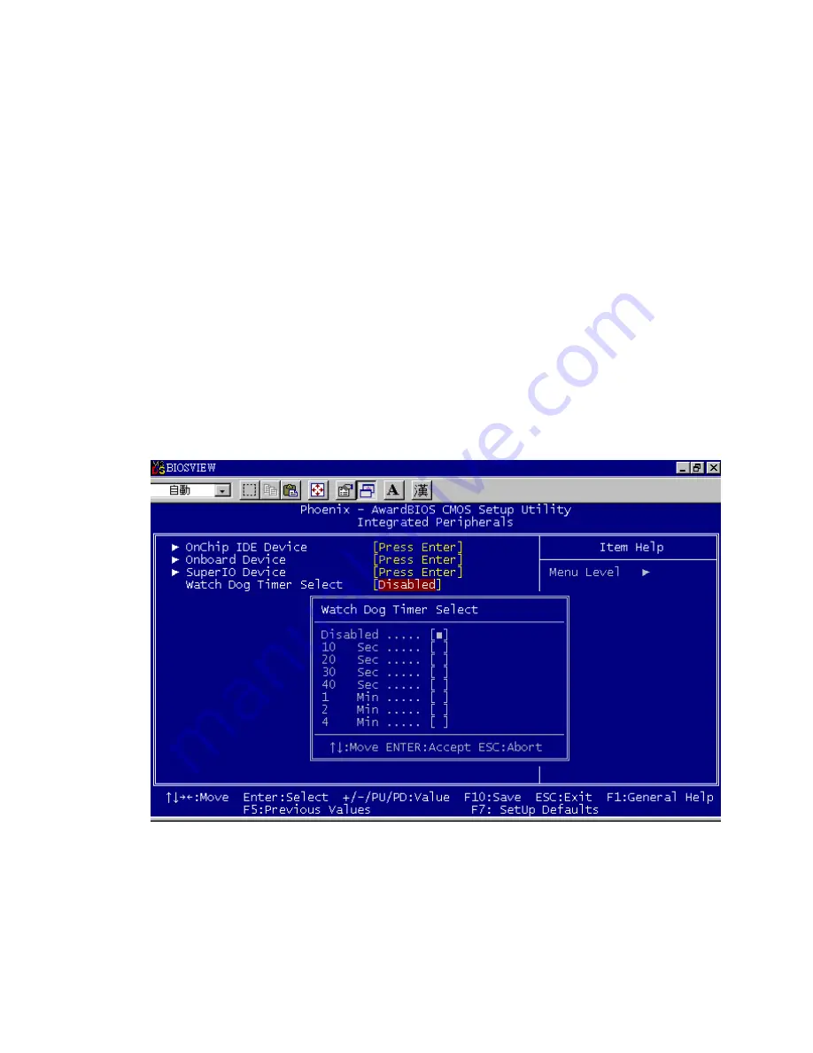
Figure 3.9: Watch Dog Timer
3.6.22
Watch Dog Timer Select
Allow User select watch Dog time or disable..
Summary of Contents for DVMB-554E
Page 12: ...12 1 General Information...
Page 20: ...20 1 6 DVMB 554E Block Diagram Figure 1 3 DVMB 554E Block Diagram...
Page 27: ...27 2 Connecting Peripherals...
Page 40: ...40 3 BIOS Setup...
Page 64: ...64 4 Chipset Installation...
Page 69: ...69 5 VGA Setup...
Page 72: ...72 3 Click Finish to complete the installation and restart the computer now or later...
Page 73: ...73 6 Video capture installation...
Page 76: ...76 Step 3 The system will show the un known devices like below window...
Page 77: ...77 Step 4 Click the below icon to specify the driver location...
Page 78: ...78 Step 5 Specify the driver under the DVMB 554E_CD 01_DVMB 554E_Driver 05_BT878 Driver...
Page 79: ...79 Step 6 Push the Next bottom to process the installation Step 7 Continuing the installation...
Page 81: ...81 Step 9 From below window we know there are 8 new items are installed...
Page 85: ...85 Step 6 Beginning the installation Step 7 Finished the installation of DVS 350 demo program...


