VESR424D Serial Server
10
USING THE RESET SWITCH TO INITIATE A HARDWARE RESET
Hold the Reset switch in for 0 to 2 seconds. The P1 LED illuminates while the switch is being
held in. Release the switch in less than 2 seconds or else the serial server will enter Console
Mode.
USING THE RESET SWITCH TO ENTER CONSOLE MODE
Hold the Reset switch for between 2 and 10 seconds. The P1 LED illuminates for the first 2
seconds then the P1 LED goes out; next, the P2 LED illuminates until the Reset switch is
released. Release the switch in less than 10 seconds or else the serial server will reset to
factory default settings. The serial server will re-boot and enter Console Mode. LED P1 will be
on while the unit is in Console Mode.
USING THE RESET SWITCH TO EXIT CONSOLE MODE
Press the Reset switch for less than 2 seconds, or remove power from the serial server, wait a
few seconds, and turn the power on again. The LEDs go back to their normal states when the
device resumes normal operation.
USING THE RESET SWITCH TO RELOAD FACTORY DEFAULT SETTINGS
Hold the Reset switch for more than 10 seconds. The P1 LED illuminates for the first 2 seconds;
then the P2 LED illuminates. After 10 seconds the P1 and P2 LEDs will illuminate. When the
switch is released, both the P1 and P2 LEDs will go out. The Ready LED will flash quickly while
the serial server re-initializes to factory default settings, and then the server will re-boot.
ETHERNET CONNECTOR
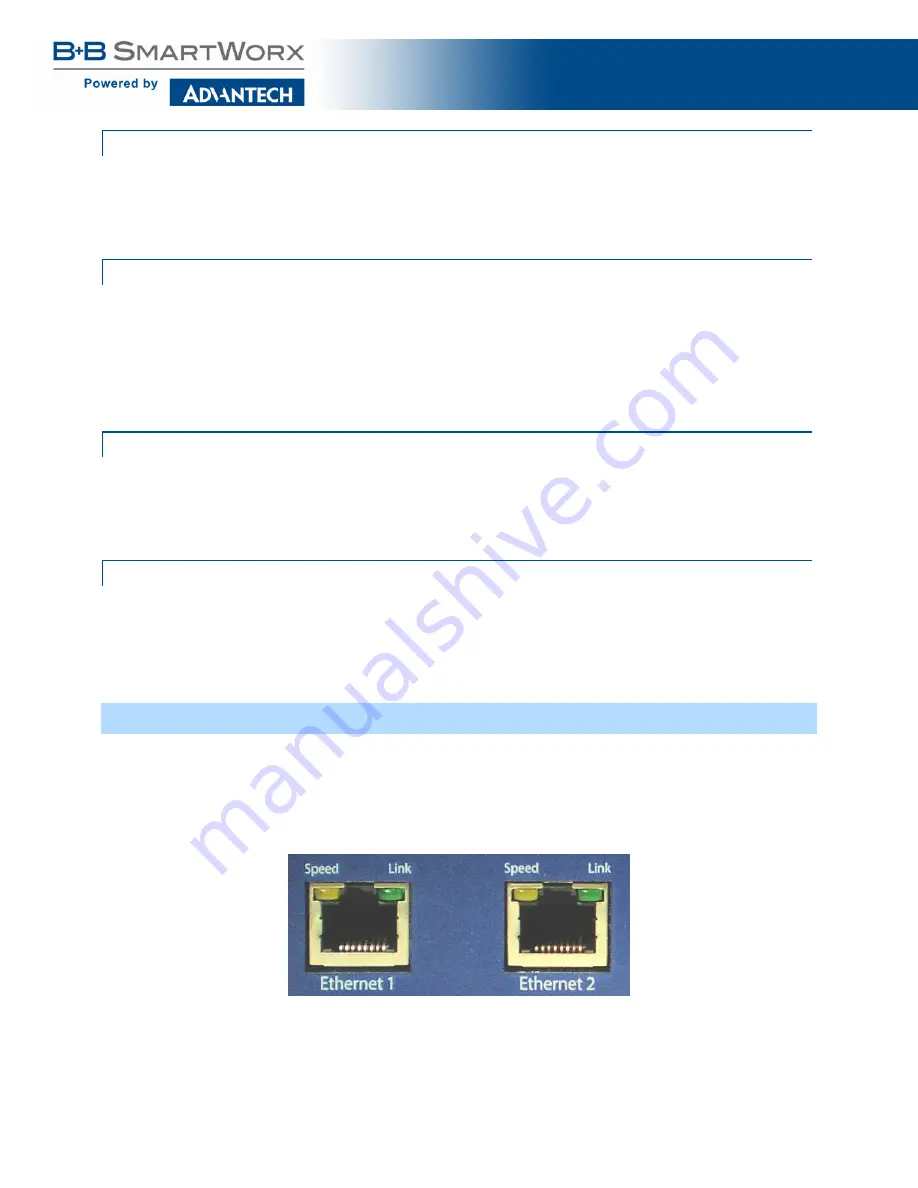
Model VESR424D is equipped with 10BaseT/100BaseTX network connections using an RJ45
receptacle. The serial server is connected to a standard Ethernet network drop using a straight-
through RJ45 (male) Ethernet cable. A second RJ45 receptacle acts as an Ethernet switch
enabling the connection of other devices to the network.
Figure 4. Ethernet Connectors
NOTE:
Refer to Appendix D for connector pinouts.


