background image

ACP-2000 User Manual

/ 用户手册 / 用戶手冊

16

3.1

The Front Panel/

前面板/前面板

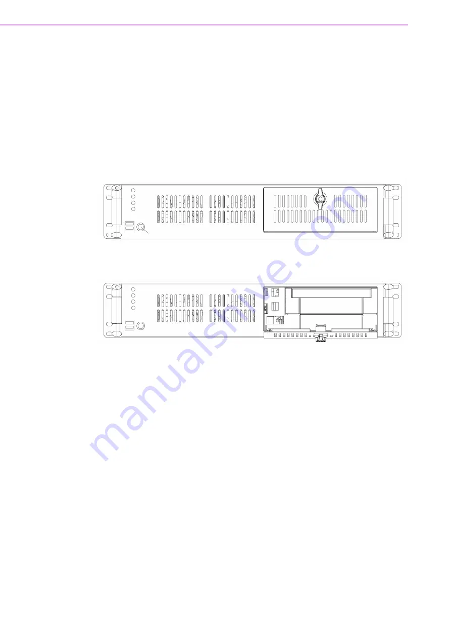
The front panel switches located behind the door are used for system power, system

reset, and alarm reset. On the left side of front panel, there are system LED status,

USB, and P/S 2 keyboard connector. On the left side of the front panel is the door

cover with a key lock.

系统控制按键区位于带锁的前门后的前面板,分别是系统电源开关,系统重启按钮与
告警重启按钮。灯号显示位于机箱箱正面右侧,显示系统电源,硬盘运作状态,温度
状态显示灯与风扇状态显示灯。LED 灯号区下方有两个 USB 与一个 PS/2 串口。
系統控制按鍵區位於帶鎖的前門後的前面板,分別是系統電源開關,系統重啟按鈕與
告警重啟按鈕。燈號顯示位於機箱箱正面右側,顯示系統電源,硬碟運作狀態,溫度
狀態顯示燈與風扇狀態顯示燈。LED 燈號區下方有兩個 USB 阜與一個 PS/2 阜。 

Figure 3.1 Front View With Door Closed/

前视图(前门关闭)/前視圖(前門關

閉)

Figure 3.2 Front View With Door Open/

前视图(前门打开)/前視圖(前門打開)

3.1.1

Switch, Button and I/O Interfaces/

开关、按钮和I/O 接口/開關、

按鈕與I/O 接口

ATX Power Switch: 

Press this switch to turn the system power on or off.

System Reset button: 

Press this switch to reinitialize the system.

Alarm Reset button: 

Press this switch to pause or stop an audible alarm.

USB port:

 Dual USB interface device to the system.

PS/2 port: 

Used in connecting PS/2 keyboard.

电源开关:按下此按钮可以接通或关闭系统电源。

系统复位按钮:按下此按钮可重启系统。

警报复位按钮:系统发生故障时(如风扇故障或机箱内温度过高等),声音报警
将被启动。按下此按钮可停止报警器的报警声。

双USB 接口:可连接多种 USB 设备,进行数据传输、备份或输入。

PS/2 接口:可连接键盘或鼠标,取决于母板设计。

電源開關:按下此按鈕可接通或關閉系統電源。

系統重置按鈕:按下此按鈕可重啟系統。

Summary of Contents for ACP-2000

Page 1: ...User Manual ACP 2000 2U Rackmount Chassis with alarm notification functions 2U 2U...

Page 2: ...formation provided in this manual is intended to be accurate and reliable However Advantech Co Ltd assumes no responsibility for its use nor for any infringements of the rights of third parties that m...

Page 3: ...ck 14 Never open the equipment For safety reasons the equipment should be opened only by qualified service personnel 15 If any of the following occurs have the equipment checked by service person nel...

Page 4: ...ssional technician please contact the service tech nician or your retailer if you need this service 24 Repair of the device may only be carried out by trained service personnel Advantech recommends th...

Page 5: ...watch the monitor or display over 1 hour each day 37 If user does not follow the instructions to set up the equipment there is a risk of opening the vent on the bottom side of the equipment The vent...

Page 6: ...ACP 2000 User Manual vi 1 2 3 18 FCC 15 1 2 19 20 21 22 1 23 VESA VESA 24 25 26 27 28 29 30 31 32 33 34 35 36 37 1 30 2 2 2 1 38 CLASS I LASER PRODUCT KLASS I LASER PRODUKT...

Page 7: ...vii ACP 2000 User Manual 1 2 3 4 5 6 7 0 C 32 F 40 C 122 F 8 9 10 11 12 13 14 15 16 17 IEC 60825 1 EN60825 1 1 2 3 18 FCC 15 1 2 19 20 CLASS I LASER PRODUCT KLASS I LASER PRODUKT...

Page 8: ...ACP 2000 User Manual viii 21 22 1 23 VESA VESA 24 25 26 27 28 29 30 31 32 33 34 35 36 37 1 30 2 2 2 1 38 www advantech com tw 26 20 1 886 2 7732 3399...

Page 9: ...best performance possible from your products If you run into technical difficulties we are here to help For the most frequently asked questions you can easily find answers in your product documentatio...

Page 10: ...te rials service time and freight Please consult your dealer for more details If you believe your product is defective follow the steps outlined below 1 Collect all the information about the problem e...

Page 11: ...xi ACP 2000 User Manual 3 RMA Return Material Authorization 4 5 RMA 1 CPU 2 3 RMA Return Mate rial Authorization 4 5 RMA...

Page 12: ...e carefully inspected the ACP 2000 mechanically and electrically before shipment It should be free of marks and scratches and in perfect working order upon receipt As you unpack the ACP 2000 check it...

Page 13: ...CPU CPU 10 Figure 2 5 Installing the Add on Card 11 2 4 Installing Disk Drives 11 Figure 2 6 Removing the Drive Bay 11 Figure 2 7 Assemble the HDD or Slim ODD 12 Figure 2 8 Assemble the HDD or ODD 12...

Page 14: ...nnectors and Switch Settings 26 Table 4 2 Hardware Switch 26 Table 4 3 Connectors 26 Table 4 4 SW1 3 27 Table 4 5 SW4 6 27 Table 4 6 SW7 9 27 Table 4 7 SW10 27 4 4 Board Layout 28 Figure 4 1 Connector...

Page 15: ...Chapter 1 1 General Information...

Page 16: ...2000 2U CT ACP 2000 e server 2U ACP 2000 19 2U IPC ACP 2000 2U CT ACP 2000 e server 2U 1 2 Specifications Construction Heavy duty steel Disk Drive Capacity One slim type ODD and two 3 5 disk drives Co...

Page 17: ...19 x 3 5 x 17 8 11 3 kg 25 3 lbs 1 3 Power Supply Options Table 1 1 Power supply options Type Single PS 2 power supply Watt 250W ATX 300W ATX 500W ATX Input rating 100 240Vac 90 264Vac 100 240Vac Out...

Page 18: ...Environmental specifications Environment Operating Non operating Temperature 0 40 C 32 104 F 20 60 C 4 140 F Humidity 10 to 85 40 C 104 F non condensing 10 to 95 40 C 104 F non condensing Vibration 0...

Page 19: ...5 ACP 2000 User Manual Chapter 1 General Information 1 5 Dimension Diagram Figure 1 1 Dimensions Diagram unit mm inch...

Page 20: ...ACP 2000 User Manual 6...

Page 21: ...Chapter 2 2 System Setup...

Page 22: ...er to the Appendix A Exploded Diagram for detailed part names A A 2 1 Removing the Top Cover Figure 2 1 Removing the Top Cover Note Use caution when installing or operating the components with the cha...

Page 23: ...3 express backplane ACP 2000P4 ACP 2000EBP ACP 2000P4 ACP 2000EBP Figure 2 2 Removing the System Cage Note Use caution when installing a motherboard We highly recommend choosing a CPU cooler listed o...

Page 24: ...ACP 2000 User Manual 10 Figure 2 3 Installing the Backplanes 2 3 Installing CPU Cards and Add on Cards CPU Card CPU Card Figure 2 4 Installing a CPU Card CPU CPU...

Page 25: ...11 ACP 2000 User Manual Chapter 2 System Setup Figure 2 5 Installing the Add on Card 2 4 Installing Disk Drives Figure 2 6 Removing the Drive Bay...

Page 26: ...ACP 2000 User Manual 12 Figure 2 7 Assemble the HDD or Slim ODD Figure 2 8 Assemble the HDD or ODD 2 5 Installing the Power Supply Figure 2 9 Installing the Power Supply...

Page 27: ...System Setup 2 6 Assembling the Handle and Brackets There is a pair of brackets and a pair of handles in the accessory box Assemble these parts on the chassis as demonstrated in the image below Figure...

Page 28: ...ACP 2000 User Manual 14...

Page 29: ...Chapter 3 3 Operation...

Page 30: ...oor cover with a key lock LED USB PS 2 LED USB PS 2 Figure 3 1 Front View With Door Closed Figure 3 2 Front View With Door Open 3 1 1 Switch Button and I O Interfaces I O I O ATX Power Switch Press th...

Page 31: ...he system power is on the power LED will turn Green A RED fan LED indicates a failed cooling fan In such cases the alarm will activate To stop the alarm s beeping press the Alarm Reset button and then...

Page 32: ...31 F An audible alarm will be activated To stop the alarm s beeping press the Alarm Reset button Inspect the fan filter and the rear section of the chassis immediately Make sure the airflow inside the...

Page 33: ...19 ACP 2000 User Manual Chapter 3 Operation 3 2 Replacing the Cooling Fan Figure 3 4 Removing the Fan Module Figure 3 5 Replacing the Cooling Fan...

Page 34: ...ACP 2000 User Manual 20 3 3 Replacing the Fan Filter Figure 3 6 Replacing the Fan Filter Figure 3 7 Replacing Front Door Filter...

Page 35: ...Chapter 4 4 Intelligent System Module...

Page 36: ...emperature CPU tem perature and voltage You can also set your own alarm settings under WISE Devi ceOn according to your requirements For detailed information please refer to the user guide for WISE De...

Page 37: ...puts 5 VDC 5 VDC 5 VSB 3 3 VDC 12 VDC 12 VDC Temperature Sensors LM75 digital temperature sensor I2C interface 30 125 C 22 257 F Fan Speed Monitor Up to 7 fans Power Monitoring Detect Redundant power...

Page 38: ...AN speed temperature monitoring Remote system monitoring through WISE DeviceOn Alarm on board buzzer and LED signal WISE DeviceOn LED CPU WISE DeviceOn LED 4 2 5 WISE DeviceOn Management Function WISE...

Page 39: ...SI command to search IPMI SUSI IPMI SUSI Blinking Warm keep beep HDD Normal Normal Data transferring Blinking FAN Normal 500rpm Normal CPU fan fail CPU CPU 500rpm Warm keep beep System fan fail 500rpm...

Page 40: ...e Connector SMBus SMBus BZ1 External Buzzer Connector Buzzer HDD1 HDD LED connector HDD LED LED PWR1 PSU Power Connector PSU SMB_MB1 I2C or SNMP connector I2C SNMP I2C SNMP RDUPG1 Power Good Input Con...

Page 41: ...ON OFF ON Connect 2 2 ON ON OFF Connect 3 1 ON ON ON Connect 3 2 Table 4 5 SW4 6 SW1 Pin4 SW1 Pin5 SW1 Pin6 SYS FAN Qty OFF OFF OFF Disable OFF OFF ON 1 FAN1 OFF ON OFF 2 FAN1 2 OFF ON ON 3 FAN1 3 ON...

Page 42: ...C_SCLK Pin 2 I2C_SDAT Table 4 9 IPMB1 Pin 1 NC Pin 3 S_SDAT_R Pin 2 S_SCLK_R Pin 4 GND Table 4 10 PMBUS1 Pin 1 V_PMBUS Pin 4 I2C_SDAT Pin 2 GND Pin 5 I2C_SCLK Pin 3 NC Table 4 11 SMB_3V_1 Pin 1 V_SMB...

Page 43: ...Pin 2 GND Pin 6 V3 3 Pin 3 GND Pin 7 V12 Pin 4 V5 Pin 8 V12 Table 4 15 TR1 4 Pin 1 TEMP_SEN1 4 Pin 2 GND Table 4 16 RDUPG1 Pin 1 GND Pin 2 PWR_FAIL_IN Table 4 17 BZ1 Pin 1 V5_DUAL Pin 2 EXT_BUZZ Table...

Page 44: ...ACP 2000 User Manual 30...

Page 45: ...Appendix A A Exploded Diagram...

Page 46: ...ACP 2000 User Manual 32 A 1 Exploded Diagram Figure A 1 Exploded Diagram...

Page 47: ...33 ACP 2000 User Manual Appendix A Exploded Diagram...

Page 48: ...without notice No part of this publication may be reproduced in any form or by any means electronic photocopying recording or otherwise without prior written permis sion from the publisher All brand...

Reviews: