TREK-570/303 User Manual
8
2.1
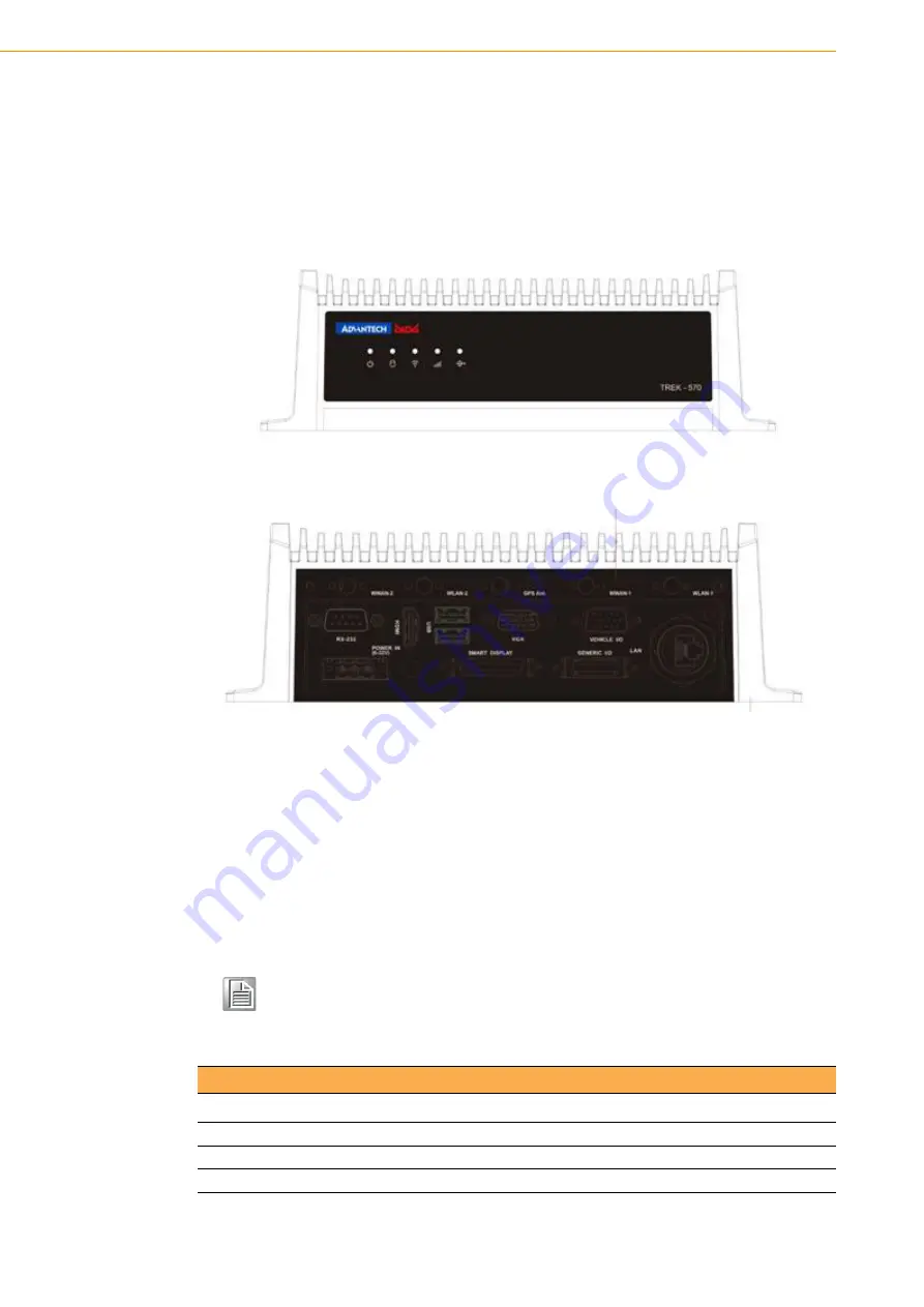
A Quick Tour of the TREK-570 Computing Box
Before starting to set up the In-Vehicle Computing Box, take a moment to become
familiar with the locations and functions of the controls, drives, connectors and ports,
which are illustrated in the figures below. When the Computer box is placed inside
truck glove cabinet or under the passenger's seat next to the driver, its front appears
as shown in Figure 2.1.
Figure 2.1 Front view of TREK-570
Figure 2.2 Rear view of TREK-570
2.2
Installation Procedures
2.2.1 Connecting the Power Cord
Connect the three pin waterproof power cord to the DC inlet of the In-Vehicle Com-
puting Box. On the open-wire end, one pin is reserved for positive voltage and is
marked, "+"; one pin is reserved for ground and is marked, "-"; and, one pin is
reserved for the ignition signal with an "ignition" mark.
Note!
Ignition on/off setting: The TREK-570 supports an ignition on/off function
so that you can power on/off the TREK-570 via the ignition signal/volt-
age and connect the TREK- vehicle ignition switch.
Table 2.1: Pin Definition of Power Cord
Pin
Definition
Color
1
+
Red
2
-
Black
3
Ignition
Orange
Summary of Contents for TREK-303
Page 1: ...User Manual TREK 570 TREK 303 In Vehicle Computing Box 7 Smart Display ...
Page 8: ...TREK 570 303 User Manual viii ...
Page 16: ...TREK 570 303 User Manual 6 ...
Page 20: ...TREK 570 303 User Manual 10 ...
Page 24: ...TREK 570 303 User Manual 14 ...
Page 28: ...TREK 570 303 User Manual 18 ...
Page 34: ...TREK 570 303 User Manual 24 ...
Page 64: ...TREK 570 303 User Manual 54 ...
Page 65: ...Appendix A A TREK 303 This appendix explains the TREK 303 detailed information ...
Page 67: ...57 TREK 570 303 User Manual Appendix A TREK 303 Pin out for TREK 303 LVDS connector ...
Page 71: ...61 ...


