March 1, 2002 Page E12
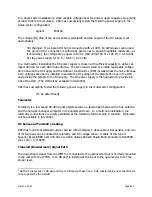
In a single sector installation a small variable voltage linear DC power supply capable of supplying
at least 1000 mA is employed. ARCi has successfully tested the following power supply in the
single sector configuration:
Agilent
E3610A
The voltage (IR) drop of the power cable is calculated and the output of the DC supply is set
appropriately.
For Example
: If a single ARCi hub is connected with a 100 ft. 18 AWG power cable (and
the ground (DC-) connection is sufficiently good so as to present negligible resistance - as
it should be), the voltage drop equals (0.95 A x 0.69 ohms/100 ft. x 100 ft.) = 0.66 volts.
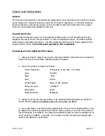
Set the power supply for (8.5 + 0.66 =) 9.2 Volts.
In a multi-sector installation the DC power supply is chosen with sufficient capacity to deliver at
least 1000 mA for each ARCi hub antenna. The DC+ lead is sized to provide reasonable voltage
drop between the DC supply and the Outdoor Junction Box (OJB) installed near the hub antennas.
A DC voltage sense pair is installed to sample the DC voltage at the distribution bus in the OJB
and provide the sample to the DC supply. The DC power supply is then adjusted to provide 8.5
Vdc at the OJB. [The OJB will be available in mid-2002].
ARCi has successfully tested the following power supply in the multi-sector configuration:
[To be determined].
Telemetry
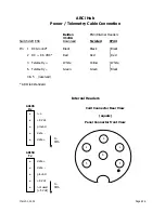
Telemetry is a low speed RS-485 signal implemented on a twisted pair between the hub antenna
and the network manager computer in the equipment room. In a multi-hub installation, the
telemetry connections are simply paralleled at the telemetry terminal strip in the OJB. [Telemetry
will be available in late 2002].
DC Sense and Telemetry Cabling
ARCi has found that shielded outdoor service rated Category 5 data cable is inexpensive, and two
of its four pairs can be utilized for telemetry and DC voltage sense. A cable of this type is
Superior Essex BBDN part #04-001-34, which utilizes Hubbell Shield Bond Connectors BC285SB
(box 100) + tool BCTK.
Transmit (Downstream) Signal Path
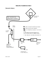
The downstream signal from the WMTS is connected to the upconverter that is normally mounted
in the rack with the WMTS. A 10 dB pad
4
is inserted at the input to the upconverter to set the
proper level.
4
ARCi will supply one 10 dB pad and two 12 dB taps with each hub. RG6 coaxial cable and connectors are
to be supplied by the installer.
Summary of Contents for AR1255
Page 4: ...March 1 2002 Page A1 A Table of Contents ...
Page 6: ...March 1 2002 Page B1 B Introduction C t t ...
Page 9: ...March 1 2002 Page C1 C System Description ...
Page 18: ...March 1 2002 Page D1 D Antenna and Frequency Planning ...
Page 24: ...March 1 2002 Page E1 E Hub Installation Detail ...
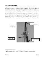
Page 29: ...March 1 2002 Page E6 Figure E4 Hub Antenna and Cable Installation Cable Access ...
Page 40: ...March 1 2002 Page F1 F Subscriber Inst l Details ...
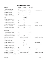
Page 46: ...March 1 2002 Page G1 G Link Budget Parameters ...


