


Page 10
Modulating Unitary Range
VA-LT206_11292016al
INSTALLATION
Installation Sequence
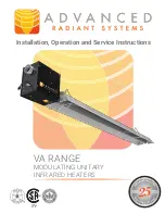
Generally, there is no unique sequence for installation of the burner or heat exchanger. A review of the job site will
usually indicate a logical installation order. However, time and expense can be saved if installation is begun at the
most critical dimension, watching for interference from overhead doors, cranes, auto lifts etc. Figure 5 provides a
general overview of the components utilized in the installation, as well as their general relationship
A general ordered sequence for installation is provided below for reference..
ADJUSTABLE
VENT ADAPTER
(S-20 AND LONGER)
TUBE
COUPLING
INSTALL "J" BOLT
AT FIRST HANGER
TUBE
FLANGE
BURNER
ASSEMBLY
GASKET
3" - 5"
COMBUSTION
TUBE
TUBE
COUPLING
HEAT
EXCHANGER
TUBE
**INSTALL BAFFLE(S)
AS REQUIRED IN THE
LAST SECTION OF TUBE
OR AS SPECIFIED IN THE MANUAL
BEND TAB
OVER END
OF TUBE
CLOSE ALL CHAIN LINKS
"S" HOOKS, "J" BOLTS
AND TURNBUCKLES OR
ANY OPEN CONNECTION
LOOSE
SCREWS
TIGHT
SCREWS
LOOSE
SCREWS
TIGHT
SCREWS
REFLECTOR
END CAP
REFLECTOR OVERLAP
APPROX. 8"
FASTEN ENDCAP
WITH SCREWS
Figure 5: General Overview of Installation


