


MNALAZIN-02
19
Integration in the Servo System / Wiring
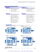
The DC power ground and the input reference command signal ground are oftentimes at a
different potential than chassis/PE ground. The signal ground of the controller must be
connected to the signal ground of the AZ drive to avoid picking up noise due to the "floating"
differential servo drive input. On all AZ drives, the DC power ground and the input command
signal ground are referenced to each other internally. In systems using an isolated DC power
supply, signal ground and/or power ground can be referenced to chassis ground. First decide if
this is both appropriate and safe. If this is the case, they can be grounded at the central
grounding point.
Wiring
Servo system wiring typically involves wiring a controller (digital or analog), a servo drive, a
power supply, and a motor. Wiring these servo system components is fairly easy when a few
simple rules are observed.
As with any high efficiency PWM servo drive, the possibility of noise and interference coupling
through the cabling and wires can be harmful to overall system performance. Noise in the
form of interfering signals can be coupled:
•
Capacitively (electrostatic coupling) onto signal wires in the circuit (the effect is more
serious for high impedance points).
•
Magnetically to closed loops in the signal circuit (independent of impedance levels).
•
Electromagnetically to signal wires acting as small antennas for electromagnetic radiation.
•
From one part of the circuit to other parts through voltage drops on ground lines.
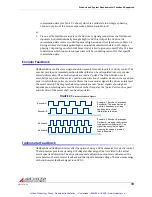
Experience shows that the main source of noise is the high DV/DT (typically about
1V/nanosecond) of the drive’s output power stage. This PWM output can couple back to the
signal lines through the output and input wires. The best methods to reduce this effect are to
move signal and motor leads apart, add shielding, and use differential inputs at the drive. For
extreme cases, use of an inductive filter card is recommended.
Unfortunately, low‐frequency magnetic fields are not significantly reduced by metal enclosures.
Typical sources are 50 or 60 Hz power transformers and low frequency current changes in the
motor leads. Avoid large loop areas in signal, power‐supply, and motor wires. Twisted pairs of
wires are quite effective in reducing magnetic pick‐up because the enclosed area is small, and
the signals induced in successive twist cancel.
Wire Gauge
As the wire diameter decreases, the impedance increases. Higher impedance wire will
broadcast more noise than lower impedance wire. Therefore, when selecting the wire gauge
for the motor power wires, power supply wires, and ground wires, it is better to err on the side
Grounding is important for safety. The grounding recommendations in
this manual may not be appropriate for all applications and system
machinery. It is the responsibility of the system designer to follow
applicable regulations and guidelines as they apply to the specific servo
system.
Artisan Technology Group - Quality Instrumentation ... Guaranteed | (888) 88-SOURCE | www.artisantg.com