


MNALAZIN-02
8
Products and System Requirements / Feedback Supported
Feedback Supported
There are a number of different feedback options available in the AZ family of analog drives.
The feedback element can be any device capable of generating a voltage signal proportional to
current, velocity, position, or any parameter of interest. Such signals can be provided directly
by a potentiometer or indirectly by other feedback devices such as Hall Sensors or Encoders.
These latter devices must have their signals converted to a DC voltage, a task performed by the
AZ drive circuitry.
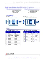
TABLE 2.3
Feedback Supported
Feedback Supported
Description
AZ
AZB
AZ_DDC
AZBDC
AZBE
AZBH
Hall Sensors for Commutation
D
D
D
D
Hall Sensors for Velocity Control
D
Single- Ended Incremental Encoder
D
Feedback Polarity
The feedback element must be connected for
negative
feedback. This will cause a difference
between the command signal and the feedback signal, called the
error
signal
. The drive
compares the feedback signal to the command signal to produce the required output to the
load by continually reducing the error signal to zero. For AZ drives, this becomes important
when using
“Encoder Feedback”
and
“Hall Sensors”
, as connecting these feedback elements
for positive feedback will lead to a motor "run‐away" condition. In a case where the feedback
lines are connected to the drive with the wrong polarity in either Hall Velocity or Encoder
Velocity Mode, the drive will attempt to correct the "error signal" by applying more command
to the motor. With the wrong feedback polarity, this will result in a positive feedback run‐away
condition. To correct this, either change the order that the feedback lines are connected to the
drive, or change Switch 4 on the DIP switch bank to the opposite setting to reverse the internal
feedback velocity polarity. See the drive datasheet for more information on DIP switch settings.
Hall Sensors
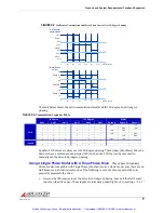
DC Three Phase (Brushless) AZ drives use single‐ended Hall Sensors for commutation
feedback, and in the special case of the AZBHxxA8 drives, for velocity control. The Hall Sensors
(typically three) are built into the motor to detect the position of the rotor magnetic field. These
sensors are mounted such that they each generate a square wave with 120‐degree phase
difference over one electrical cycle of the motor. Depending on the motor pole count, there
may be more than one electrical cycle for every motor revolution. For every actual mechanical
motor revolution, the number of electrical cycles will be the number of motor poles divided by
2. For example:
•
a 6‐pole motor contains 3 electrical cycles per motor revolution
•
a 4‐pole motor contains 2 electrical cycles per motor revolution
•
a 2‐pole motor contains 1 electrical cycle per motor revolution.
The drive powers two of the three motor phases with DC current during each specific Hall
Sensor state:
Artisan Technology Group - Quality Instrumentation ... Guaranteed | (888) 88-SOURCE | www.artisantg.com