


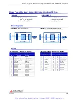


FIGURE 2.4
AZ-series Pin Layouts
PIN 1b
PIN 1a
PIN 11a
PIN 11b
PIN 1
PIN 16
P1 - Signal
Connector
P2 - Power
Connector
0.10in [2.54mm]
[55.88mm]
2.20in
0.10in [2.54mm]
PIN 1
PIN 11
PIN 16
P1 - Signal
Connector
P2 - Power
Connector
PIN 1
[2.54mm]
[55.88mm]
2.20in
0.10in
AZ6 and AZ12 Drives
AZ20 Drives
MNALAZIN-02
11
Products and System Requirements / Pin Layout
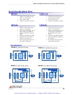
Pin Layout
The diagrams below show the pin layout and location on AZ drives, as seen from the PCB
where the drive is mounted. Note that AZ20 drives uses a double row for the power header.
More detailed dimensional information can be found in
“Physical Dimensions” on page 39
and
in
“Mating Connectors” on page 24.
Artisan Technology Group - Quality Instrumentation ... Guaranteed | (888) 88-SOURCE | www.artisantg.com