7
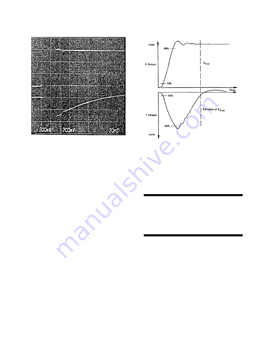
Fig. 4.2. Typical Simultaneous E and T Output
Signals.
Fig. 4.3. Output Rise Time Measurement.
CAUTION
Do not use a metal screwdriver for this
adjustment; there is a possibility of high-bias
voltage leakage on the printed circuit that could
cause a shock.
due to slewing effects and large signal bandwidth
timing resolution when the rise time is optimized
considerations within the charge loop, the large-
with this control. Because of the high voltages
signal rise time is slightly longer than that
that are present inside the case when the
specified at the E output for an amplitude of 1.0V
preamplifier is operating, a small plastic
unterminated (0.5 V terminated). Again, however,
screwdriver or a TV tuning tool should be used for
this has no impact on a typical timing experiment
this adjustment.
since the slope of the leading edge is maintained
over the whole dynamic range of the preamplifier,
and since discriminator thresholds are typically
set well below 1.0 V.
In Fig. 4.2, the rise time of the T output appears
to be longer than that for the E output but this is
not necessarily true. The 10% and 90% check
points on the E rise time are based on the E
final
level, which is less than the initial overshoot. On
the other hand, the 10% and 90% check points on
the T rise time are based on the peak level of the
initial overshoot, which is relatively more than the
final value for the E output.
4.5. COMPENSATION ADJUSTMENT
A bandwidth compensation adjustment is
accessible to the user of the 142AH. This control
can be adjusted through the bottom of the case
without opening the unit. It is used to tune the
preamplifier to the particular detector that is
connected in order to provide the fastest optimal
rise time of the T and E output signals for the best
When the 142 AH Preamplifier is shipped from
the factory, the compensation adjustment has
been set for the specified rise time resolution for
a 0-pF input capacity. For optimum results for
other input capacities, the control should be
adjusted under actual operating conditions.
If the control has been adjusted for optimum
bandwidth for a specific input capacity and the
input circuit is then changed to provide less
capacity, control readjustment is necessary so
that the preamplifier will not oscillate. If the input
capacity is increased from the value for which the
adjustment has been made, the preamplifier
should be stable and should not oscillate.


