collectors connected for diagonal flow the reverse
return principle, this optimum performance conditions
will now exist.
Systems with rows of collectors of unequal size, but
fitted with balancing valves, may now be adjusted.
Open all balancing valves completely and let the
system run for several minutes. The row(s) which
feel(s) warmer to the touch than the other(s), is
currently receiving less flow then it should be
optimum performance. Throttle the valve(s) of the
other (cooler) row(s) step-by-step, each time waiting
for a few minutes, and check the temperature. Once
all rows feel uniformly cool, the system is balanced
and operates at optimum performance.
COLLECTOR REPAIR
In case of a leak in the collector, one of two easy and
permanent on-site repair methods is recommended
and will not void the warranty:
If the leak is at the header where the riser tube is
welded to the header, or a leak is anywhere in the
riser tube if the system is located in areas
experiencing frost, use method one.
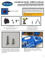
1) Referring to the figure below, locate the tube to be
isolated. (End tube has been shown for clarity.) Using
a sharp utility knife, very carefully cut away
approximately 1” of the tube at both headers. Drive a
#10 - #12 sheet metal screw, preferable stainless, into
the hole in the header. The screw must be between ½”
and 3/” long. DO NOT OVERTIGHTEN! If the screw
strips out, or if the repair leaks, use a larger screw.
If the leak is located in a riser tube in non-freezing
climates only, use method two.
2) Locate the leak and with a sharp utility knife cut
through the tube at the leak. Cut the web lengthwise
on each side of the tube about an inch above and
below the leak area, enough so that either section of
the tube may be pushed downward.
Insert repair plugs, Part No. 30143 in the tube
openings, one above and one below the leak area.
User a #0 Phillips head screwdriver inserted into the
hollow conical shaped end of the plug to push the
plug into place. Bring the damaged section of the tube
back to its former position, restoring the original
appearance of the collector.
Advance Power, Inc.
1-888-228-9694
6331 North State St
Calpella, CA 95470
[email protected]
www.advancepower.net