background image

NetVanta 3000 Series Hardware Installation Guide

 Unit Installation

61200860L1-34L

Copyright © 2006 ADTRAN, Inc.

65

NetVanta 3205 and NetVanta 3305

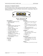
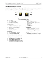
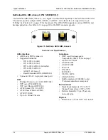
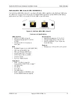
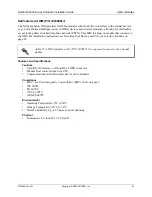
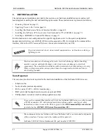
Figure 28.  Repositioning the Mounting Bracket for Wall Mounting the NetVanta 3205/NetVanta 3305

Instructions for Wall Mounting NetVanta 3205/NetVanta 3305

Step

Action

1

Remove the mounting ears. Rotate them 90

o

 so that the portion of the bracket with the 

mounting holes is flush with the bottom of the chassis, and reattach them to the chassis (see 
Figure 28). 

2

Decide on a location for the unit. Keep in mind that the unit needs to be mounted at or below 
eye level so that the LEDs are viewable. 

Important! 

Mount the chassis with LEDs facing to the 

side as shown in 

Figure 28

 (not facing up or down).

3

Prepare the mounting surface by attaching a board (typically plywood, 3/ 4-inch  to 1-inch  
thick) to a wall stud. 

Important!

 Mounting to a stud ensures stability. Using sheetrock anchors 

may not provide sufficient long-term stability. 

4

Have an assistant hold the unit in position as you install two #6 to #10 (1 1/ 2-inch or greater in 
length) wood screws through the unit’s brackets and into the mounted board. See Figure 28.

5

Proceed to the steps given in 

Supplying Power to the Unit 

on page 66.

To avoid damaging unit, use only the screws included in shipment when attaching 
mounting ears to the chassis. 

Summary of Contents for NetVanta 3000 Series

Page 1: ...ork Interface Module 1200878E1 L1 NetVanta E1 FE1 G 703 Network Interface Module 1200866E1 L1 NetVanta Serial Network Interface Module 1200867L1 NetVanta SHDSL Network Interface Module 1200869E1 L1 Ne...

Page 2: ...this publication Software Licensing Agreement Each ADTRAN product contains a single license for ADTRAN supplied software Pursuant to the Licensing Agreement you may a use the software on the purchase...

Page 3: ...0L1 34L Copyright 2006 ADTRAN Inc 3 Conventions Notes provide additional useful information Cautions signify information that could prevent service interruption or damage to equipment Warnings provide...

Page 4: ...an a cordless type during an electrical storm There is a remote risk of shock from lightning 3 Do not use the telephone to report a gas leak in the vicinity of the leak 4 Use only the power cord power...

Page 5: ...network or premises wiring using an FCC compatible modular jack which is compliant with Part 68 and requirements adopted by ACTA 7 The following information may be required when applying to the local...

Page 6: ...se limits are designed to provide reasonable protection against harmful interference when the equipment is operated in a commercial environment This equipment generates uses and can radiate radio freq...

Page 7: ...B EN 55022 Class B EN 55024 EN 61000 3 2 EN 61000 3 3 FCC Part 15 Class A EN 55022 Class A EN 55024 EN 61000 3 2 EN 61000 3 3 FCC Part 15 Class A EN 55022 Class A EN 55024 EN 61000 3 2 EN 61000 3 3 1...

Page 8: ...ndicates the maximum number of terminals that can be connected to a telephone interface The termination on an interface may consist of any combination of devices subject only to the requirement that t...

Page 9: ...Product Service CaPS department to have an RMA number issued CaPS should also be contacted to obtain information regarding equipment currently in house or possible fees associated with repair Identif...

Page 10: ...ADTRAN Custom Extended Services ACES program offers multiple types and levels of installation and maintenance services which allow you to choose the kind of assistance you need This support is availab...

Page 11: ...gn 28 NetVanta 3205 Rear Panel Design 28 NetVanta 3305 30 NetVanta 3305 Features and Specifications 30 Network Interface Modules and Dial Backup Interface Modules Supported 31 NetVanta 3305 Shipping C...

Page 12: ...DN BRI DIM P N 1200865L1 59 NetVanta ISDN S T DIM P N 1200875L1 60 NetVanta Serial DIM P N 1200886L1 61 Unit Installation 62 Tools Required 62 Mounting Options 63 Rack Mounting NetVanta 3000 Series 63...

Page 13: ...3448 Front Panel Layout 40 Figure 15 NetVanta 3448 Rear Panel Layout 40 Figure 16 NetVanta 56K 64K NIM 47 Figure 17 NetVanta T1 FT1 NIM 48 Figure 18 NetVanta T1 NEBS NIM 49 Figure 19 NetVanta T1 FT1 D...

Page 14: ...List of Figures NetVanta 3000 Series Hardware Installation Guide 14 Copyright 2006 ADTRAN Inc 61200860L1 34L...

Page 15: ...3205 DC Version Only 76 Table A 5 ADSL Connector Pinouts 76 Table A 6 WAN DDS Connector Pinouts 77 Table A 7 WAN T1 Connector Pinouts 77 Table A 8 WAN E1 Connector Pinouts 77 Table A 9 DSX 1 Connecto...

Page 16: ...List of Tables NetVanta 3000 Series Hardware Installation Guide 16 Copyright 2006 ADTRAN Inc 61200860L1 34L...

Page 17: ...s The unit is powered by a 12 VDC power supply AC to DC power adapter included This section includes a list of features a list of shipping contents and a description of the unit s front and rear panel...

Page 18: ...800 mA 7 5 W NetVanta 3120 Shipping Contents Each NetVanta 3120 unit is shipped in its own cardboard shipping carton Open each carton carefully and avoid deep penetration into the carton with sharp o...

Page 19: ...during bootup the unit will stay in bootstrap mode Since the unit has no serial port Telnet has been built into the boot code The default IP address is 10 10 10 1 If the factory default switch is pre...

Page 20: ...mand line interface refer to the AOS Command Reference Guide also included on your CD NetVanta 3130 Features and Specifications The NetVanta 3130 offers the following features Fixed port Ethernet rout...

Page 21: ...e refer to Repair and Return on page 9 Shipments of the NetVanta 3130 include the following items NetVanta 3130 Base Unit ADTRAN OS System Documentation CD Quick Start Guide Warranty card External 12...

Page 22: ...ctors used to access the 10 100BaseT Ethernet switch Power Connection The rear panel has a 12V input for the DC power supply included in the shipment Please refer to Supplying Power to the Unit on pag...

Page 23: ...atency queuing LLQ weighted fair queuing WFQ class based weighted fair queuing and DiffServ marking Built in alert and logging mechanisms Network Address Translation NAT NAPT 1 1 NAT port translation...

Page 24: ...each carton carefully and avoid deep penetration into the carton with sharp objects After unpacking the unit inspect it for possible shipping damage If the equipment has been damaged in transit immedi...

Page 25: ...anta 3200 Rear Panel Interfaces and LEDs SLOT 1 NET DBU Option Slot The SLOT 1 NET DBU option slot supports various plug in Network Interface Modules NIMs These option modules are described in the sec...

Page 26: ...tion on router configuration for a specific application refer to the quick configuration documents provided on your ADTRAN OS System Documentation CD For details on the command line interface refer to...

Page 27: ...ial Backup Interface Modules Supported The NetVanta 3205 supports a variety of interchangeable network interface modules NIMs and dial backup interface modules DIMs The NIMs available for the NetVanta...

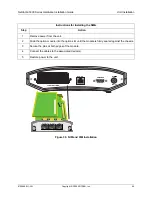
Page 28: ...AN OS System Documentation CD Quick Start Guide Warranty card NetVanta 3205 Front Panel Design The NetVanta 3205 front panel is shown below Front panel LED descriptions are given in Table 1 on page 42...

Page 29: ...The Ethernet port provides the following 10BaseT or 100BaseT with a single connector Auto negotiation CSMA CD IEEE 802 3 compatibility CONSOLE Interface The CONSOLE interface is an EIA 232 serial por...

Page 30: ...or details on the command line interface refer to the AOS Command Reference Guide also included on your CD NetVanta 3305 Features and Specifications Modular Network Interface 56K 64K T1 FT1 T1 FT1 NEB...

Page 31: ...nd Dial Backup Interface Modules Supported The NetVanta 3305 supports a variety of interchangeable network interface modules NIMs and dial backup interface modules DIMs The NIMs available for the NetV...

Page 32: ...mounting ears screws ADTRAN OS System Documentation CD Quick Start Guide Warranty card Detachable AC power cord NetVanta 3305 Front Panel Design The NetVanta 3305 front panel is shown below Front pan...

Page 33: ...national routers are shipped with a universal input lump in line supply with the appropriate cables All of the 1U high products have universal power supplies and are shipped with the appropriate cable...

Page 34: ...1 T1 FT1 DSX 1 Dual T1 E1 FE1 E1 FE1 G 703 or ADSL Annex A or Annex B SHDSL or serial interface Dial backup to any PPP compliant device Analog modem ISDN BRI U or S T or serial Dial Backup Interface M...

Page 35: ...to the NIM providing dial backup capability Refer to Installing Dial Backup and Network Interface Modules on page 68 for more details NetVanta 3430 Shipping Contents Each NetVanta 3430 unit is shipped...

Page 36: ...ont panel contains a Compact Flash slot for non volatile configuration storage and compressed code storage ADTRAN supports only ADTRAN provided compact flash 16 MB to 1 GB see list of part numbers on...

Page 37: ...odular access router designed for cost effective branch office connectivity over MPLS Frame Relay multilink Frame Relay point to point PPP multilink PPP or Ethernet networks It offers an integrated 8...

Page 38: ...tegral stateful inspection firewall protects against Denial of Service DoS attempts Flash memory supports multiple images of AOS Interchangeable Network Interface Modules NIMs Dial backup to any PPP c...

Page 39: ...to the NIM providing dial backup capability Refer to Installing Dial Backup and Network Interface Modules on page 68 for more details NetVanta 3448 Shipping Contents Each NetVanta 3448 unit is shipped...

Page 40: ...he LEDs this front panel contains a Compact Flash slot for non volatile configuration storage and compressed code storage ADTRAN supports only ADTRAN provided compact flash 16 MB to 1 GB see list of p...

Page 41: ...Vanta 3448 itself cannot be powered by this port 8 Switch Port Interfaces Ports 1 through 8 are RJ 45 connectors used to access the fully managed 10 100BaseT Ethernet switch 10 100BaseT Ethernet Inter...

Page 42: ...y For the ISDN BRI DIM green solid indicates that the negotiation with the switch is complete Green flashing The unit is in dial backup Red solid An alarm condition is occurring on the DBU interface o...

Page 43: ...nta E1 FE1 NIM P N 1200868E1 L1 on page 52 NetVanta E1 FE1 G 703 NIM P N 1200878E1 L1 on page 53 NetVanta Serial NIM P N 1200866E1 L1 on page 54 NetVanta SHDSL NIM P N 1200867L1 on page 55 NetVanta AD...

Page 44: ...tart Guide 15 foot RJ 45 to RJ 45 cable ADTRAN P N 3125M008 A NetVanta T1 FT1 DSX 1 NIM 61202863L1 Shipments of the T1 FT1 DSX 1 NIM include the following items T1 FT1 DSX 1 Network Interface Module Q...

Page 45: ...RJ 11 to RJ 11 cable ADTRAN P N 3127014 NetVanta ADSL NIM Annex B 1200889E1 L1 Shipments of the ADSL NIM Annex B include the following items ADSL Network Interface Module Quick Start Guide 7 foot RJ...

Page 46: ...DIM include the following items Serial Dial Backup Interface Module Quick Start Guide 7 foot RJ 45 to RJ 11 cable ADTRAN P N 3125M007 A Option modules are intended to be serviced by qualified service...

Page 47: ...tional DIM is required for dial backup applications Figure 16 NetVanta 56K 64K NIM Features and Specifications Operating Modes Dedicated DDS leased line DDS Interface Supported Standards AT T TR 62310...

Page 48: ...403 Bellcore TR 194 Line Rate 1 544 Mbps 75 bps Line Code AMI or B8ZS Framing D4 SF or ESF FT1 Line Rate DS0 channelized multiples of 64 kbps Input Signal 0 to 36 dB DS1 Line Build Out 0 7 5 15 22 5...

Page 49: ...65016 ANSI T1 403 Bellcore TR 194 Line Rate 1 544 Mbps 75 bps Line Code AMI or B8ZS Framing D4 SF or ESF FT1 Line Rate DS0 channelized multiples of 64 kbps Input Signal 0 to 36 dB DS1 Line Build Out 0...

Page 50: ...DS0 channelized multiples of 56 64 kbps Input Signal 0 to 36 dB DS1 Line Build Out 0 7 5 15 22 5 dB long 0 to 655 ft short DS0 Assignment Programmable Connector RJ 48C DSX 1 Interface Line Interface D...

Page 51: ...016 ANSI T1 403 Bellcore TR 194 Line Rate 1 544 Mbps 75 bps Line Code AMI or B8ZS Framing D4 SF or ESF FT1 Line Rate DS0 channelized multiples of 64 kbps Input Signal 0 to 36 dB DS1 Line Build Out 0 7...

Page 52: ...E1 Interface Supported Standards ITU G 703 ITU T G 704 CRC 4 ITU T G 823 ITU T G 797 Line Rate 2 048 Mbps 50 PPM Line Code AMI or HDB3 Framing FAS with optional CRC 4 FE1 Line Rate Channelized timeslo...

Page 53: ...G 704 CRC 4 ITU T G 823 ITU T G 797 Line Rate 2 048 Mbps 50 PPM Line Code AMI or HDB3 Framing FAS with optional CRC 4 FE1 Line Rate Channelized timeslot in multiples of 64 kbps Receiver Sensitivity 3...

Page 54: ...optional DIM is required for dial backup applications Figure 23 NetVanta Serial NIM Cable length for the Serial NIM should not exceed 25 feet SERIAL DBU Features and Specifications Operating Mode DTE...

Page 55: ...etwork termination CPE SHDSL Interface Supported Standards ITU T G 991 2 SHDSL Line Rate 200 to 2312 kbps in 64k increments Line Code TC PAM Connector RJ 45 Clock Source CPE Operating Mode Network CO...

Page 56: ...rface ADSL over POTS Annex A Supported Standards ITU G 992 1 G dmt ITU G 992 2 G lite ITU G 992 3 ADSL2 G dmt bis ITU G 992 5 ADSL2 ANSI T1 413 Issue 2 Reach Extended ADSL READSL2 Connector RJ 1C 6 pi...

Page 57: ...ures and Specifications ADSL Interface ADSL over ISDN Annex B Supported Standards ITU G 992 1 G dmt Connector RJ 11C 6 pin jack inner pair ATM Multiple Protocol over AAL5 RFC2684 PPP over ATM RFC2364...

Page 58: ...refer to Installing Dial Backup and Network Interface Modules on page 68 Features and Specifications Features ITU V 90 compliant Async Standards EMC see Electromagnetic Compatibility EMC Table on pag...

Page 59: ...Backup and Network Interface Modules on page 68 Features and Specifications Features Clear Channel and bonding mode 1 call protocols Network support for 64 kbps 1 B channel or 128 kbps 2 B channels D...

Page 60: ...ork Interface Modules on page 68 Features and Specifications Features Clear channel and bonding mode 1 call protocols Network support for 64 kbps 1 B channel or 128 kbps 2 B channels D channel switch...

Page 61: ...installation instructions see Installing Dial Backup and Network Interface Modules on page 68 Features and Specifications Features 5 pin RS 232 interface vial host RJ 45 DBU connector Modem flow cont...

Page 62: ...3000 Series are Ethernet cable Network cable module dependent DSX 1 cable T1 FT1 DSX 1 module only DBU cable dial backup functions require an optional DIM Phillips head screwdriver rack mounting appli...

Page 63: ...a rack If you have purchased P N 4200368L1 which includes the VPN Accelerator Card with the NetVanta 3305 install the card before mounting the unit See Installing the NetVanta VPN Accelerator Card in...

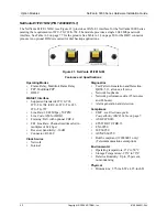
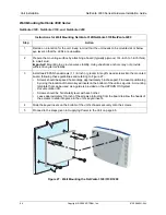
Page 64: ...anchors may not provide sufficient long term stability 3 Install two 8 PAN headscrews 1 1 2 inch or greater in length wood screws into the mounted board following these guidelines and referring to Fig...

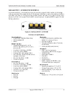
Page 65: ...eds to be mounted at or below eye level so that the LEDs are viewable Important Mount the chassis with LEDs facing to the side as shown in Figure 28 not facing up or down 3 Prepare the mounting surfac...

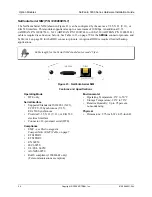
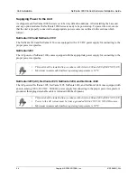
Page 66: ...3200 The AC powered NetVanta 3200 comes equipped with the appropriate power supply for connecting to the proper power receptacles NetVanta 3205 AC NetVanta 3305 NetVanta 3430 and NetVanta 3448 The AC...

Page 67: ...ctrically isolated from the AC source Use only copper conductors when making power connections Install unit in accordance with Article 400 and 364 8 of NEC NFPA 70 The branch circuit overcurrent prote...

Page 68: ...ling a module Improper installation may result in damage to the modules Instructions for Installing the DIMs Step Action 1 Remove power from the unit 2 If the NIM is already in the NetVanta chassis re...

Page 69: ...for Installing the NIMs Step Action 1 Remove power from the unit 2 Slide the option module into the option slot until the module is firmly seated against the chassis 3 Secure the pins at both edges o...

Page 70: ...ower consumption of the card does not exceed 2 watts Figure 31 NetVanta VPN Card Installation The Accelerator Card is intended to be installed only by qualified personnel Instructions for Installing t...

Page 71: ...ged your static electricity pick up the SODIMM by its top or sides Do not touch the gold contacts at the bottom 6 Gently insert the module into the memory slot at a slight angle approximately 30 degre...

Page 72: ...0 Series Hardware Installation Guide 72 Copyright 2006 ADTRAN Inc 61200860L1 34L Figure 32 SODIMM Installation Keyed Slots Figure 33 SODIMM Installation Applying Pressure Figure 34 SODIMM Installation...

Page 73: ...and connected to the network For more information on configuration for a specific application refer to the quick configuration documents provided on your ADTRAN OS System Documentation CD For details...

Page 74: ...Unit Installation NetVanta 3000 Series Hardware Installation Guide 74 Copyright 2006 ADTRAN Inc 61200860L1 34L...

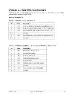
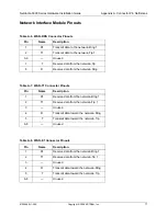
Page 75: ...witch ports only 2 TX2 Transmit Negative PoE negative rail switch ports only 3 RX1 Receive Positive PoE negative rail switch ports only 4 5 Unused 6 RX2 Receive Negative PoE negative rail switch ports...

Page 76: ...a Terminal Ready input 5 SG Signal Ground 6 DSR Data Set Ready output Tied to pin 1 7 RTS Request to Send input 8 CTS Clear to Send output Tied to pin 1 9 RI Ring Indicate output Connection directly t...

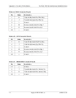
Page 77: ...e network Tip 8 R Receive data from the network Ring Table A 7 WAN T1 Connector Pinouts Pin Name Description 1 R1 Receive data from the network Ring 1 2 T1 Receive data from the network Tip 1 3 Unused...

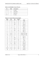
Page 78: ...Receive data from the DTE Ring 1 5 T1 Receive data from the DTE Tip 1 6 8 Unused Table A 10 G 703 Connector Pinouts Pin Name Description 1 R Transmit data toward the DTE Ring 2 T Transmit data toward...

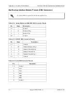
Page 79: ...A 13 Serial to Cable Connector Pinouts Serial Pin V 35 Pin X 21 Pin EIA 530 Pin Name 1 P 2 2 TD_A 2 U N A 24 ETC_A 3 Y N A 15 TCLK_A 4 V 6 17 RCLK_A 5 R 4 3 RD_A 6 F N A 8 DCD_A 7 H N A 20 DTR_A 8 C...

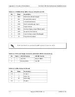
Page 80: ...ns Table A 14 Analog Modem and ISDN BRI DBU Connector Pinouts Pin Name Description 1 3 Unused 4 R Network Ring 5 T Network Tip 6 8 Unused Table A 15 ISDN S T DBU Connector Pinouts Pin Name Description...

Page 81: ...specifications 59 60 shipping contents 45 NetVanta ISDN S T DIM 60 features and specifications 60 shipping contents 45 46 NetVanta Serial DIM 61 DIMs supported 23 27 31 35 39 DSX 1 interface pinout 7...

Page 82: ...s 41 NetVanta VPN Accelerator Card 70 installation 70 Network Interface Modules NIMs 43 installation 68 NetVanta 56K 64K NIM 47 features and specifications 47 48 shipping contents 44 NetVanta ADSL NIM...

Page 83: ...Vanta 3130 21 NetVanta 3200 24 NetVanta 3205 AC 28 NetVanta 3205 DC 28 NetVanta 3305 32 shipping contents domestic NetVanta 3430 35 NetVanta 3448 39 shipping contents international NetVanta 3430 36 Ne...

Page 84: ...Index NetVanta 3000 Series Hardware Installation Guide 84 Copyright 2006 ADTRAN Inc 61200860L1 34K...

Reviews: