background image

Installing the Switch

NetVanta 1570-24-370W QSG

4

617101574PF1-13A

3. Confirm that the power is connected properly. The 

SYSTEM

 LED should be 

ON

 (see 

“SYSTEM Status LED”

).

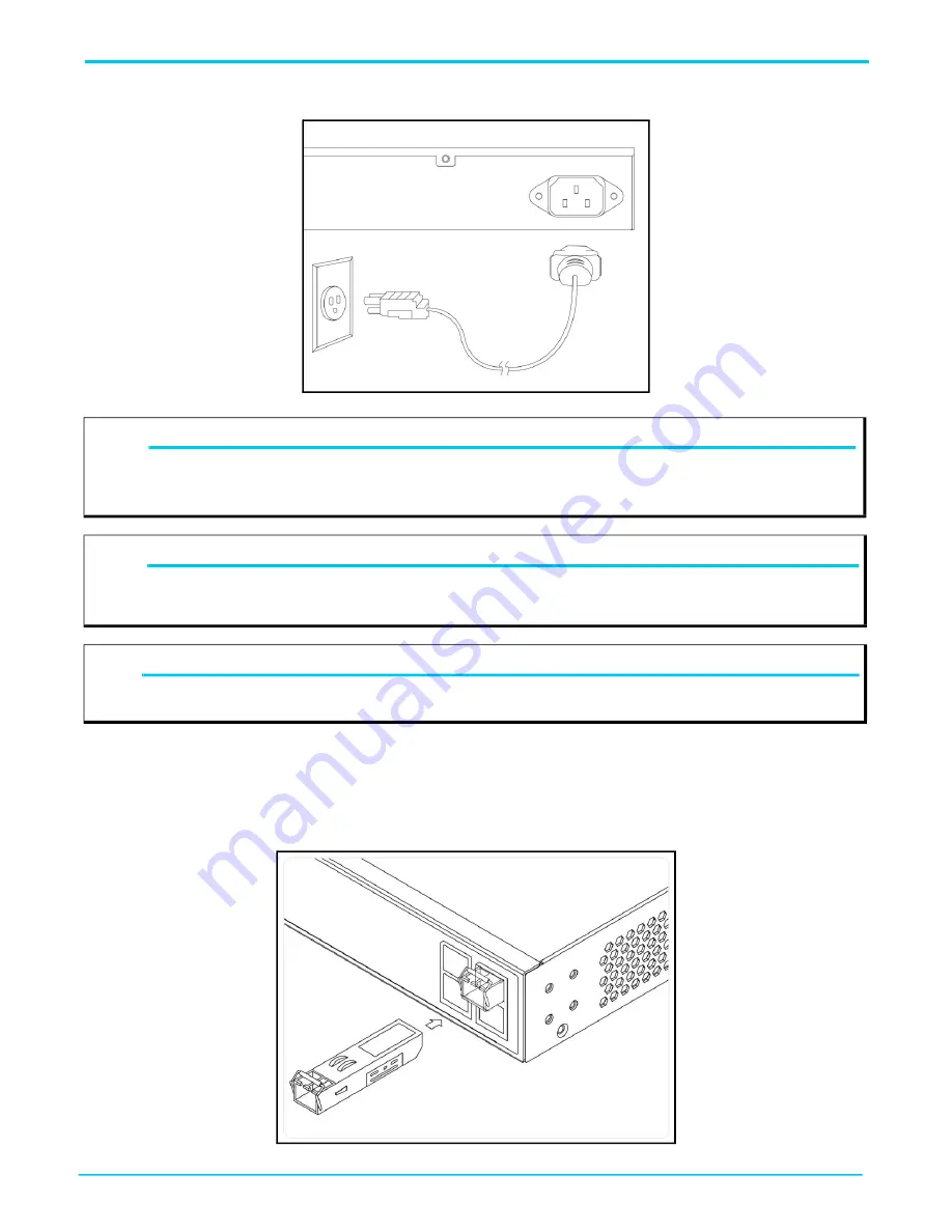
Figure 6. Connecting the AC Power Cord

Install SFP+ Modules

You can install or remove an SFP+ module from an SFP+ port without having to power off the switch. To install an SFP+ module, complete the 

following steps.

1. Insert the module into the appropriate SFP+ port. 

2. Press firmly to ensure that the module seats properly into the connector.

Figure 7. Installing an SFP+ Module into an SFP+ Port

NOTE

g

The installation of this product must comply with the national, state and local electrical code requirements, as applicable. The AC branch 

circuit overcurrent protection must be a fuse or circuit breaker rated 125 VAC, 20 Amps maximum or 250 VAC, 16 Amps maximum. A 

readily accessible disconnect device that is suitably approved and rated must be incorporated in the field wiring.

CAUTION!

f

It is recommended that an external AC Surge Protection Device be installed at the AC input connection to the local AC-Powered product. 

The Surge Protection device should provide L-N, L-G, and N-G protection. It is also recommended that the device contains a visual 'GOOD' 

indicator.

WARNING!

f

This equipment incorporates double pole/neutral fusing. If the neutral fuse opens and the line fuse does not open, voltage could still be 

present in the unit

Summary of Contents for NetVanta 1570-24-370W

Page 1: ...this equipment NetVanta 1570 24 370W SYSTEM LNK ACT SPD PoE CONSOLE USB MODE RESET 1 2 3 4 5 6 7 8 9 10 11 12 13 14 15 16 17 18 19 20 21 22 23 24 25 26 27 28 LINK ACT SPD Mode LED SYS LED CONSOLE Port...

Page 2: ...of the chassis Insert the provided screws and tighten them with a screwdriver to secure the brackets Figure 3 Attaching Brackets to the Switch 2 Position the chassis in the stationary equipment rack A...

Page 3: ...e 5 Attaching the Rubber Feet Supplying Power to the Switch To connect the AC power cord to the switch complete the following steps 1 Connect the AC power cord to the AC power receptacle on the rear p...

Page 4: ...st comply with the national state and local electrical code requirements as applicable The AC branch circuit overcurrent protection must be a fuse or circuit breaker rated 125 VAC 20 Amps maximum or 2...

Page 5: ...Select OK to change the PC s IP address 3 Power up the switch to be initially configured and wait until it has finished its start up processes 4 Connect the PC to any port on the switch using a stand...

Page 6: ...EEE 802 3af PoE and IEEE 802 3at PoE standards By default the PoE switch discovers and provides power to IEEE compliant PDs it also supports legacy PDs The total PoE budget for the switch is 370W Each...

Page 7: ...no active network cable connected or has not established a link to connected device Oth erwise the port may have been disabled through the switch user interface SFP Ports Green On The port is enabled...

Page 8: ...derstand the abnormal state e g exceeding operating temperature range and take correspond ing actions to resolve Port Status LED is OFF when the LINK ACT SPD LED is LIT The port is not connected or th...

Page 9: ...des provide additional information for this ADTRAN product available online at https supportcommunity adtran com Configuring the CLI in ASE Configuring QoS in ASE Configuring Layer 2 Services in ASE C...

Reviews: