ADTRAN NetVanta 1560-48-740W Quick Start Manual Download Page 1

Quick Start

Overview

This quick start describes how to install, configure, and troubleshoot the NetVanta 1560-48-740W, 48-port Managed GbE 740W PoE+ 

Switch. Figures 1 and 2 show the Front and Rear Panel layouts of the switch. 

“Installing the Switch” 

on page


1

“Initially Configuring the Switch” 

on page


4

“Power Over Ethernet (PoE)” 

on page


5

“Understanding the Status LEDs” 

on page


6

“Using the MODE Button” 

on page


7

“Troubleshooting the Switch” 

on page


7

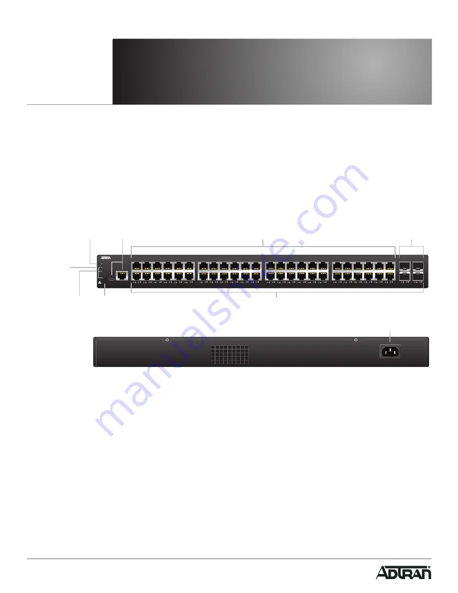
Figure 1. Front Panel Layout

Figure 2. Rear Panel Layout

Installing the Switch

Package Contents

NetVanta 1560-48-740W switch

AC power cord

DB-9 to RJ-45 cable

Micro-USB to USB cable

Four adhesive rubber feet

Mounting kit (two brackets and eight screws)

Quick Start

f


WARNING!

The NetVanta 1560-48-740W is intended for indoor use only. Ethernet, PoE cables, and attached equipment are intended for use within 

the same building with equipotential bonding, and not intended to be placed in separate buildings or structures. Failure to deploy as 

described could result in permanent damage from lightning or other electrical events and voids the warranty.

NetVanta 1560-48-740W

SYSTEM

LNK/ACT/SPD

PoE

CONSOLE

USB

MODE/RESET

1

2

3

4

5

6

7

8

9

10

11

12

13

14

15

16

17

18

19

20

21

22

23

24

51

52

25

26

27

28

29

30

31

32

33

34

35

36

37

38

39

40

41

42

43

44

45

46

47

48

49

50

PoE

Mode LED

MODE

Button

Port Status

LEDs

LINK/ACT/SPD

Mode LED

SYS

LED

CONSOLE

Port

10/100/1000

RJ-45 with PoE+

1G/10G

SFP+ Ports

AC Line: 100-240V 50-60Hz

AC Line: 100-240V 50-60Hz

Power Connection

NetVanta 1560-48-740W

48-port Managed GbE 740W PoE+ Switch

March 2020

617108148PF2-13D

P/N: 17108148PF2

Summary of Contents for NetVanta 1560-48-740W

Page 1: ...art f WARNING The NetVanta 1560 48 740W is intended for indoor use only Ethernet PoE cables and attached equipment are intended for use within the same building with equipotential bonding and not inte...

Page 2: ...g steps 1 Attach the mounting brackets to both sides of the chassis Insert the provided screws and tighten them with a screwdriver to secure the brackets Figure 3 Attaching Brackets to the Switch 2 Pl...

Page 3: ...top and sides of the unit for sufficient air flow Connect AC Power To connect the AC power cord to the switch complete the following steps 1 Connect the AC power cord to the AC power receptacle on th...

Page 4: ...face of the switch using the switch s default IP address as shown below g NOTE The factory default IP address of the switch is 10 10 10 1 and the subnet mask is 255 255 255 0 If the switch is connecte...

Page 5: ...the two console ports USB RJ45 available in the switch To establish the connection to the console port the following are needed PC with VT100 terminal emulation software Micro USB to USB cable or a DB...

Page 6: ...LED On The port status LEDs are displaying link status network activity and the speed of each port LED Color State Description PoE On The RJ 45 port status LEDs are displaying the PoE powering status...

Page 7: ...faults 7 12 seconds Flashing Green All LEDs are ON Symptoms Possible Causes Suggested Solutions System LED is OFF The switch is not receiving power 1 Check if correct power cord is connected firmly to...

Page 8: ...0 C to 45 C Storage Temperature 40 F to 158 F 40 C to 70 C Relative Humidity 10 to 95 percent non condensing Electrical Power Supply 100 to 240 VAC 50 60 Hz 11A Documentation for ADTRAN Network Solut...

Reviews: