


6
617101568PF2-13A
g
NOTE
There are many terminal emulation applications available on the web. PuTTY, SecureCRT, and HyperTerminal are a few examples.
Complete the following steps:
1. Connect a Micro USB cable to the micro USB CONSOLE port or connect a DB-9 to RJ-45 serial cable to the RJ-45 CONSOLE port.
2. If using a Micro USB cable, connect the other end of the USB cable to a USB port on the PC. If using an RJ-45 serial cable, connect the other end to the serial
terminal on the PC.
3. If using the Micro USB cable to connect the switch, check if the USB drivers are automatically installed in the PC. If not install manually.
4. Open a VT100 terminal session using the following settings: 115200 baud; 8 data bits; no parity bits; 1 stop bit; and no flow control. Press <Enter> to activate
the CLI.
5. Login with the default user name (
admin
) and password (
password
).
Power Over Ethernet (PoE)
The switch provides the PoE on the 48 Ethernet ports shown in
. PoE provides the ability to detect attached Powered Devices (PDs), and deliver power to
the PD via Ethernet cabling. The switch is fully compliant with the IEEE 802.3af PoE and IEEE 802.3at PoE+ standards. By default, the PoE switch discovers and
provides power to IEEE-compliant PDs, it also supports legacy PDs. The total PoE budget for the switch is 370W. Each port can provide a maximum of 30W in
compliance to the IEEE 802.3at PoE+ standard. All 48 ports cannot have 30W PD devices as this exceeds the PoE budget of the switch; a combination of few 30W
PDs and low power PDs can be used as long as the sum of load is less than 370W.
Understanding the Status LEDs
The LEDs on the front panel provide you with switch status checking and monitoring. The following section describes the three types of LEDs.
SYSTEM Status LED
The SYSTEM Status LED indicates if the switch is powered up correctly or if a system alarm has been triggered for troubleshooting.
LINK/ACT/SPD Mode LED
The LINK/ACT/SPD Mode LED indicates the port status LEDs are displaying in link/act/speed mode.
PoE Mode LED
The PoE Mode LED indicates the port status LEDs are displaying in PoE mode.
Port Status LEDs
The Port Status LEDs indicate the current status of each port in either Link/Act/Speed mode or PoE mode. By pressing the
MODE
button for less than two seconds,
you can change LED modes from
LINK/ACT/SPD
mode to
PoE
mode, to check the port status in each mode.
When LINK/ACT/SPD Mode LED Is Lit
When the LINK/ACT/SPD Mode LED is lit, the link/act/spd status is indicated by the LED behavior.
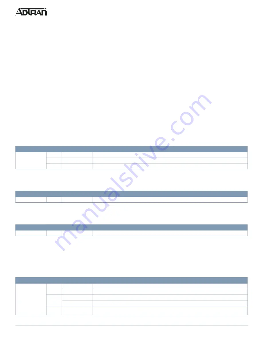
LED
Color
State
Description
SYSTEM
Off
The switch is not receiving power.
On
The switch is powered ON correctly.
On
An abnormal state, such as exceeding operating temperature range, has been detected in the switch.
LED
Color
State
Description
LINK/ACT/LED
On
The port status LEDs are displaying link status, network activity, and the speed of each port.
LED
Color
State
Description
PoE
On
The RJ-45 port status LEDs are displaying the PoE powering status of each port.
LED
Color
State
Description
RJ-45 Ports
On
The port is enabled and established a link to connected device, and the connection speed is 1000 Mbps.
Flashing
The port is transmitting/receiving packets, and the connection speed is 1000 Mbps.
On
The port is enabled and established a link to connected device, and the connection speed is 10/100 Mbps.
Flashing
The port is transmitting/receiving packets, and the connection speed is 10/100 Mbps.
Off
The port has no active network cable connected or has not established a link to connected device. Otherwise, the
port may have been disabled through the switch user interface.


