61287802F1C-13A
3
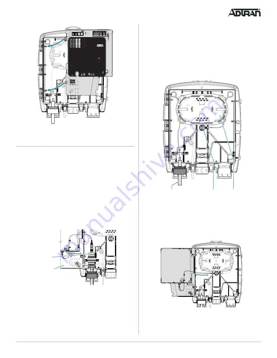
Figure 5. ONT
Route the Fiber Connection
To route the fiber connection, complete one of the following options:
■
“OptiTap® NID (P/N: 1187771G1)”
■
“Fiber Splice SC/APC Bulkhead NID (P/N: 1187770G1)”
g
NOTE
Clean all optical surfaces before connecting cables.
OptiTap
®
NID (P/N: 1187771G1)
To install the fiber connection using the Optical Connector, refer to
, and complete the following steps.
f
CAUTION!
Ensure that the fiber cable entering the unit is UL Listed Optical Fiber
Cable and contains no metallic members or other electrical
conductive materials.
Figure 6. Optical Connector
1. Route the incoming fiber cable through the port identified in
.
2. Connect the optical connector.
3. Connect a fiber jumper from the top of the optical connector to the
bottom of the SC/APC connector located at the bottom edge of the
ONT.
4. Route the fiber jumper so that when the ONT is
closed, the fiber is
not pinched.
ETH 1
ETH 2
ETH 3
ETH 4
POTS 3
POTS 4
POTS 2 POTS 3 POTS 4
POTS 1
TA 374 2nd GEN
1287803F1C
TIP
RING
ETH 1
ETH 2
ETH 1
ETH 2
12V , 1.25A
POTS 2
POTS 1
POWER
GPON
POTS 2
POTS 1
TELCO ACCESS ONLY
TELEPHONE TROUBLESHOOTING
1. Identify the bad line.
2. Disconnect the plug from the appropriate POTS jack and plug
any working telephone into that jack.
• If the telephone works, there is a problem inside the house.
Take necessary steps to repair problem before reconnecting POTS jack.
• If the telephone does not work, contact your service provider.
3. Remove the telephone and replace the plug into the POTS jack.
4. Close the unit.
This device complies with Part 15 of the FCC rules. Operation is subject to
the following two conditions:
• This device may not cause harmful interference
• This device must accept any interference received, including
interference that may cause undesired operation.
CLASS 1 LASER
PRODUCT
ACCESSORY
COMMUNICATION
SERVICE EQUIPMENT
E187790
901 Explorer Blvd.
Huntsville, AL 35806 USA
www.adtran.com
Optical
Connector
Fiber Jumper
(Route as Shown)
Fiber Splice SC/APC Bulkhead NID (P/N: 1187770G1)
To install the fiber connection using the bulkhead connector, complete the
following steps:
1. Route the incoming fiber cable through the port identified in
f
CAUTION!
If the fiber cable has a metallic trace wire, do not bring the trace wire
inside the NID housing. It is recommended to cut off the trace wire at
least 6 inches from the NID housing and insulate it, or cut off the trace
wire and bury underground.
Figure 7. SC/APC Bulkhead Connector
2. Route the fiber in the fiber tray and terminate it at the bulkhead
connector.
3. Connect a fiber jumper from the bulkhead connector to the SC/APC
connector at the bottom of the ONT (refer to
).
Figure 8. Fiber jumper to the ONT
4. Route the fiber jumper so that when the ONT is closed, the fiber is
not pinched.
BulkHead Connector
Fiber Tray
Incoming Fiber
Cable
Note:
Connect the Fiber Jumper
to the BulkHead Connector


