background image

61287781F1C-13A

3

Installation Overview

To install the C424G ONU, you will need to complete the following steps:

“Step 1: Mounting Option”

“Step 2: Connect VoIP (POTS)”

“Step 3: Connect Ethernet”

“Step 4: Connect Power”

“Step 5: Connect Uninterrupted Power Source (UPS)”

Required tools

Standard technician tools and those listed below are required for installing the C424G ONU:

Phillips-head screwdriver

Two, RJ-11 connectors

Four, RJ-45 connectors

Wire strippers

RJ-11 and RJ-45 crimpers

PON power meter with wavelength filtering

Fiberscope or videoscope

For fiber optic connections, the following is required:

ODC Fiber cleaning tool

Step 1: Mounting Option

Installation consists of positioning the C424G ONU on either a desktop, or mounting it on a wall.

Desk Top Installation

With a desk mount, ensure the C424G ONU is not located in direct sunlight and is not located next to any thermal obstructions. 
To attach the C424G ONU to the base, complete the following steps:

1. Snap the base on to the bottom of the C424G ONU.
2. Thread the fiber cable through the opening in the base. If there is excess fiber, carefully wrap it around the Fiber Tray.

Remove the plug from the SC/APC Connector and insert the fiber cable. Retain this plug and insert it in the fiber connection when the 
fiber cable is not connected. This will protect the optical portion of the connection.

Wall Mount Installation

To wall mount the C424G ONU, complete the following steps:

1. Decide on a location for the C424G ONU. Mount below eye-level so the LEDs are visible.
2. Attach a 1/4 inch mounting board (typically plywood) to the wall. If the wall is drywall construction, ensure the mounting board is 

supported by the wall studs.

3. Install two #8 Pan Head screws (1 inch or greater in length) using the key holes on the bottom of the C424G ONU as location 

markers. Leave approximately 1/4 inch protruding from the mounting surface.

4. Slide the C424G ONU over the Pan Head screws and exert a small amount of downward pressure to ensure that the top of the slots 

are resting on the shafts of the Pan Head screws.

Step 2: Connect VoIP (POTS)

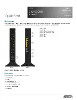
Refer to 

Figure 1

 and insert the RJ-11 connector in to one of the two VoIP ports.

Summary of Contents for CenturyLink C424G

Page 1: ... and rear of the C424G ONU Figure 1 C424G ONU Front and Rear FEATURES The C424G ONU supports the following features Reset Button USB Four Ethernet Ports Two VoIP POTS Ports 2 4 GHz and 5 0 GHz WiFi 12 VDC Power Adapter USB Port 2 Front Rear 1 3 4 5 6 Item 1 Reset Item 2 USB Item 3 Ethernet Connections Item 4 VoIP POTS Connections Item 5 Power Item 6 UPS Item 7 WPS 7 FTTP C424G ONU 2P 4GE WIFI June...

Page 2: ...ttery charged WiFi The WiFi function allows you to connect wireless devices without entering a pre shared password key in the device WiFi supports the following protocols 802 11 b g n support on 2 4GHz radio with 2x2 MIMO antenna design 802 11 a n ac support on 5GHz radio with 4x4 MU MIMO antenna design g NOTE The pre shared password key is the default password and is located on the label of the C...

Page 3: ...ottom of the C424G ONU 2 Thread the fiber cable through the opening in the base If there is excess fiber carefully wrap it around the Fiber Tray Remove the plug from the SC APC Connector and insert the fiber cable Retain this plug and insert it in the fiber connection when the fiber cable is not connected This will protect the optical portion of the connection Wall Mount Installation To wall mount...

Page 4: ...er to the installation material that is provided with the UPS To connect UPS refer to Figure 1 and connect a UPS cable from the source to the UPS port on the rear of the unit g NOTE ADTRAN offers a UPS Cable assembly P N 1287402G1 for this connector The UPS Power Alarm Connections Table below defines each pin on the connector UPS Power Alarm Table The following table below provides a pinout of the...

Page 5: ...Link Connected Link Lost INTERNET PPP AUTO DETECTION Green Red During Auto Detection unit will alternate between Green and Red until unit is detected REGISTRATION ID Internet PPP and or IPOE LED during Registration ID will function as follows CONNECTION FAILURE Red Red indicates Auto Detection failed LED will remain Red for 5 seconds then Auto Detection will resume AUTHENTICATED W PPP CREDENTIALS ...

Page 6: ...UB LIC IP CONNECTION VERIFIED 4 Green Green Flashing Static IP verified and connected LAN to WAN and WAN to LAN connectivity in process ETHERNET 1 4 2 Off Green Green Flashing Fast Unit is not connected Link is up Data is being sent or received USB 2 Off Green Green Flashing Fast Power Off or no device connected Device connected Data is being sent or received WIFI 2 4GHZ WIFI ENABLED DISABLED 2 Of...

Page 7: ...pairs be attempted in the field Repair services may be obtained by returning the defective unit to ADTRAN Refer to the warranty for further infor mation Field support for software is provided through upgrade facilities VOIP 1 2 VOIP SIP REGISTRATION 2 2 Off Green Green Flashing Yellow Yellow Green Flashing Red VoIP Disabled in the Gateway VoIP Traffic Registered and Active VoIP Traffic is being tr...

Page 8: ...ILABILITY 1 800 827 0807 61287781F1C 13A Documentation for ADTRAN Network Solutions products is available for viewing and download directly from the ADTRAN Support Community website Go to https supportforums adtran com welcome Registration is required ADTRAN offers training courses on our products including customized training and courses taught at our facilities or at customer sites For inquiries...

Reviews: