background image

4

617600132F1-13A

3. For a Voice connection on the 854-v6 only, insert an RJ-11 cable into one of the telephone ports (labeled 

Tel 1

 or 

Tel 2) 

until there is an audible 

“click”.

4. Before connecting to the service provider interface, clean the optical Interfaces of the SC/APC connectors.
5. Insert the fiber cable into the 

WAN

 port on the bottom of the gateway.

Connecting the Power Supply

1. Connect the end of the power adapter to the 

Power

 port on the rear panel of the gateway

2. Plug other end of the power adapter into the wall outlet.
3. Confirm that the power is connected properly. The 

Power

 LED should be lit on the front of the gateway.

Resetting the Gateway

A reset button is available if the device needs to be rebooted. To reboot the device, press the 

Reset

 button on the rear panel of the gateway for 

5 seconds 

or less

. To reset the device to custom defaults, press the 

Reset

 button for 

5 seconds


or more.

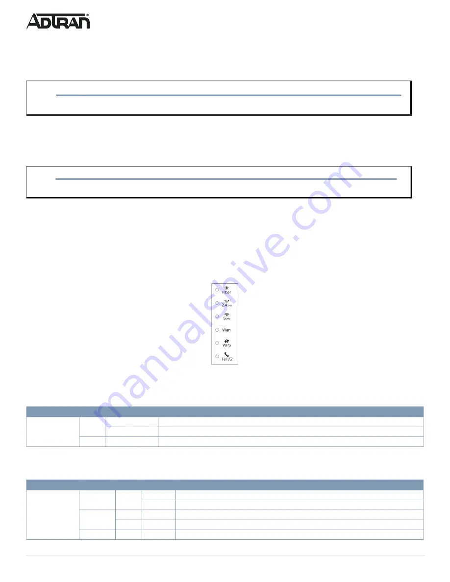
Understanding the Status LEDs

The LEDs on the back panel of the device enable you to monitor the device status. This section describes the four types of LEDs available on the 

gateway. See 

Figure 3

 for details.

Figure 3. Status LEDs

Fiber Status LED

The 

Fiber

 status LED indicates the state of an inserted Fiber SFP module. 

2.5G WAN LED

The 

2.5G WAN

 status LED indicates the state of the 2.5G WAN connection on the gateway.

CAUTION!

f

To prevent breaking the fiber, do not exceed the fiber bend radius of 3.5 in (8.9 cm).

NOTE

g

Alternately, the device may be powered by a supported third-party UPS which may be connected via 7-pin molex connector, labeled 

UPS

.

LED

Color

State

Description

Fiber

Green

On

Fiber optic connection is UP.

Flashing

Fiber optic connection is discovering or activating the ONT on the PON.

None

Off

Fiber optic connection is DOWN.

LED

Color

State

Description

WAN

2.5.Gbps

Green

On

WAN is UP at 2.5 Gbps speed.

Flashing

WAN connection is transferring data.

1000/

100 Mbps

Orange

On

WAN is UP at 1000/100 Mbps speed.

Flashing

WAN connection is transferring data.

None

Off

WAN connection is DOWN.

Summary of Contents for 617600026F1

Page 1: ...way WARNING f Read all warnings cautions notes and installation instructions before installing or servicing this equipment f ATTENTION Lisez tous les avertissements et mises en garde avant l installation de cet équipement ou la réalisation de toute opération de maintenance Device Part Number 854 6 Wi Fi 6 2 5G Router 617600028F1 854 v6 Wi Fi 6 2 5G Router with Voice 617600026F1 f WARNING f CAUTION...

Page 2: ... desktop and wall mount Be sure to route and secure the fiber and cables in a manner that will prevent damage These options are described below Desktop Installation This device can be placed on a desk or table The following table shows the recommended minimum distance in feet and meters between ADTRAN equipment and household appliances to reduce interference NOTE g Refer to the national state and ...

Page 3: ...ubscriber interfaces refer to Figure 2 and complete the following 1 For a WAN connection do either of the following 2 5Gb WAN insert a Cat 5E or better Ethernet cable into the port labeled 2 5G WAN until there is an audible click SFP WAN insert a compatible SFP module into the SFP cage at the bottom of the Router 2 For an Ethernet LAN connection insert a Category 5E or better RJ 45 cable into one ...

Page 4: ...re Understanding the Status LEDs The LEDs on the back panel of the device enable you to monitor the device status This section describes the four types of LEDs available on the gateway See Figure 3 for details Figure 3 Status LEDs Fiber Status LED The Fiber status LED indicates the state of an inserted Fiber SFP module 2 5G WAN LED The 2 5G WAN status LED indicates the state of the 2 5G WAN connec...

Page 5: ...the phone line ports on the 854 v6 device LED Color State Description 2 4GHz 5GHz Green On Wi Fi radio is UP Flashing Wi Fi radio is transferring data None Off Wi Fi connection is DOWN LED Color State Description WPS Green On Wi Fi Protected Setup complete Flashing Wi Fi Protected Setup pairing in progress None Off Wi Fi Protected Setup inactive LED Color State Description Tel 1 2 Green On Telepho...

Page 6: ...ukt P N 617600028F1 17 aufgeführt NOTE g It is strongly suggested that the power supply a 5 foot 1 5 m power cord included with the 854 v6 be connected to a surge suppressor device which can have its own extension cable The surge protection device should provide L N L G and N G protection It is also recommended that the device contains a visual GOOD indicator NOTE g Changes or modifications not ex...

Page 7: ...e AC branch circuit socket outlet must be installed near the equipment and must be easily accessible The RJ 45 jacks are not used for telephone line connection Device Part Number 854 6 Wi Fi 6 2 5G Router 617600028F1 854 v6 Wi Fi 6 2 5G Router with Voice 617600026F1 f WARNING f AVERTISSEMENT f WARNUNG Read all warnings cautions notes and installation instructions before installing or servicing thi...

Page 8: ...of Conformity Products bearing the marking comply with the following EU directives EMC Directive 2014 30 EU Low Voltage Directive 2014 35 EU WEEE Directive reference 2012 19 EU If this product has telecommunications functionality it also complies with the requirements of the following EU Directive RED 2014 53 EU Compliance with these directives implies conformity to harmonized European standards t...

Page 9: ...rmitted for devices in the bands 5250 5350 MHz and 5470 5725 MHz shall be such that the equipment still complies with the e i r p limit iii the maximum antenna gain permitted for devices in the band 5725 5850 MHz shall be such that the equipment still complies with the e i r p limits specified for point to point and non point to point operation as appropriate and iv the worst case tilt angle s nec...

Reviews: