background image

User Manual of TV5600-B01 Series Dispensing Control System 


63


6)


Remote network port: Network port number for visual communication 


8.02.04 Otherfactory parameters 


Description 


1.


Vendor parameter password setting 

2.


Language selection 

3.


Stop  button  lift  reset:  Set  whether  the  motor  is  reset  at  the  same  time 
when  the  stop  button  is  lifted.  Generally,  it  refers  to  the  external 
emergency stop self-locking button 

4.


Start  button  plus  pause  function:  Press  the  start  button to  pause  in  the 
running process 

5.


Extended  IO  settings:  Connect  to  external  expansion  IO  board,  external 
input and output portscan be added 

6.


Jog distance: The distance of manual jog 

7.


Corner  speed  smoothing  level:  Increasing  the  corner  speed  smoothing 
level  will  improve  the  overall  processing  efficiency  and motion  stability, 
but will also cause a large single-axis start-stop speed at the corner 

8.


Track splitting accuracy: The controller divides all the graphics into small 
line segments of equal length0. The track splitting precision is the length 
of the small line segments. If the setting is too small, the controller will 
calculate  too  much  and  affect  the  motion  effect.  It  is  generally 
recommended that the value be greater than the distance that the motor 
rotates by 1/50 of a turn 

9.


Z-axis lift during positioning: Whether Z is raised when positioning 

10.


Automatic speed smoothing: Motion smoothing 

11.


Vendor service period setting 

12.


User service periodsetting 

13.


Restore backup system parameters 

14.


Restore parameters to factory defaults 

8.02 Motor speed related parameters 

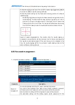
1.  ->In  handheld  box  system  parameter  interface  ->  Press  [

Motor  speed]  ->

enter 

parameters -> 

Summary of Contents for DJ1600V1-A01

Page 1: ...I TV5600 B01 Series Dispensing Control System User Manual ...

Page 2: ...User Manual of TV5600 B01 Series Dispensing Control System 2 ...

Page 3: ...design engineer electrical technician and installer Repair and operation personnel Instructions and reading conventions for this manual When using this CNC system for the first time please read every chapter of this manual carefully to better use the system functions Note on terminologyin this manual and reading conventions The combined model refers to a set of split type dispensing CNC system con...

Page 4: ...onnect the surge absorption diodes to the product in the required direction otherwise the product will be damaged Ensure the power switch is OFF before inserting or removing plug or disassembling chassis Overhauling Ensure the power is OFF before overhauling or components replacement Make sure to check failures after short circuit or overloading and then restart the machine after troubleshooting D...

Page 5: ...rate 12 hours day Routine Inspection Routine Confirm environmental temperature humidity dust or foreign objects Confirm abnormal vibration and noise Check whether vents are blocked by yarn etc Regular Check One year Check whether solid components are loose Confirm whether terminal block is damaged Copyright 2013 ADTECH Shenzhen Technology Co Ltd Reprint or reproduction of any content in this manua...

Page 6: ...tion 23 4 02 Dual position function configuration 26 4 03 Visual dispensing function configuration 26 4 04 Glue gun rotation workpiece rotation function configuration 28 Chapter 5 Reset Settings 30 5 01 Explanation of reset parameters 30 5 01 Pulse transmission mode setting 31 5 02 Reset direction setting 32 5 03 Pulse equivalent setting 32 5 04 Origin and limit signal test 32 5 05 Reset 33 Chapte...

Page 7: ... 8 02 Motor speed related parameters 63 8 03 Standby parameters 64 8 03 01 Standby position setting 64 8 03 02 Automatic dispensing related parameters 65 8 04Automatic needle aligning setting 66 8 05 Password management 67 8 06 Introduction to other system parameters 68 8 07 File conversion 69 8 08 Custom functions 70 Chapter 9 Monitoring Operation 72 Chapter 10 Common Functional Operation Guideli...

Page 8: ...nstructions 88 Appendix III MCD904 ADT 8849 and AMC1600 Program Update Method 95 Appendix IV TV5600 B01 Handheld Box Program Update Method 100 Appendix 5 UpdatingRemote Program viaHandheld Box USB Flash Drive 101 Appendix 6 MCD904 Wiring Instructions 103 Appendix VII ADT8849 Wiring Instructions 115 Appendix VIII AMC1600P Wiring Instructions 124 ...

Page 9: ...s can be regarded as the spatial generalization of the polar coordinate system It takes the coordinate origin as the reference point and is composed of azimuth elevation and distance denoted as P r θ φ as shown below The cylindrical coordinate system can also be regarded as a spatial extension of polar coordinates as shown below Plane polar coordinate system Spherical coordinate system Cylindrical...

Page 10: ...es coordinate system is as follows 1 02 Dispenser coordinate system After getting the dispenser we will find the coordinates of each axis are displayed on the interface of the handheld box The structure of the coordinate system of the general dispenser mechanism is shown as figure below Due to the combination of the modules and the combination style the dispenser mechanism also has the following s...

Page 11: ... length a pulse travels in millimeters i e L P Speed Indicates the speed of the axis movement unit mm s Acceleration Indicates the speed of the axis speed change unit mm s2 Starting speed The starting speed of general stepping motor should be less than 3L mm s and the starting speed of servo motor should be less than 5L mm s Maximum speed 20L mm s for stepping motor 50L mm s for servo motor Z look...

Page 12: ...ntrol and IO port operations and constitutes a set of split full three dimensionaland high precision dedicated motion control system Note HMI is optional and if provided only WEINVIEW touch screen and its interface project files are provided to achieve the burning function Product model Numb er of axes Digit al inpu t Digital outpu t Controller Handheld box HMI optional DJ904V1 A01 3 24 6 MCD904 T...

Page 13: ...C Working temperature 45 C Storage temperature 40 C 55 C Working humidity 40 80 Storage humidity 0 95 2 02 Software features 2 6 axis interpolation support space line space arc and spline curve Speed look ahead algorithm automatic arc corner speed and automatic rounding inflection point Support standard Modbus ASCII Modbus RTU and Modbus TCP communication protocols Support rich processing instruct...

Page 14: ... Support Lua scripting function designed to solve non standard processes Lua script is named after main lua and is stored in the root directory of the controller disk Scripting is supported by the following product models 2 03 Structure size 2 03 01 MCD904 structure diagram 2 03 02 ADT 8849structure diagram DJ904V3 A01 A02 DJ904V4 A 01 A02 DJ8849V1 A01 A02 DJ8849V2 A01 A02 DJ8849V3 A01 A02 DJ1600V...

Page 15: ...User Manual of TV5600 B01 Series Dispensing Control System 15 Front view Side view Side view ...

Page 16: ...User Manual of TV5600 B01 Series Dispensing Control System 16 2 03 03 AMC 1600structure diagram 2 03 04 TV5600 B01structure diagram Dimensional drawing of AMC 1600E ...

Page 17: ...User Manual of TV5600 B01 Series Dispensing Control System 17 2 04 Description of handheld box buttons Keypad layout TV5600DJ Dimensional drawing ...

Page 18: ...ual low speed positive direction Z axis manual low speed negative direction A axis manual low speed positive counterclockwise direction A axis manual low speed negative clockwise direction B axis manual low speed positive direction B axis manual low speed negative direction C axis manual low speed positive direction C axis manual low speed negative direction Manual high speed when any axis is pres...

Page 19: ...rface find the instructions that meet the conditions according to the requirements Display processing file graphic in the monitoring editing interface Global menu keys Switch between monitoring and editing interface Manage processing program files Set file related parameters Set system parameters Test the status of the offline card signal input and signal output and test whether the handheld box b...

Page 20: ...ries Dispensing Control System 20 diagnosis interface and then press the key to enter the version information interface as shown below Generally only the handheld box version number and the controller version number need attention ...

Page 21: ...cessing speed trajectory speed is different the number of processing times is different and the glue on off time is different which leads to different parameters for different processed products This type of parameters is classified as file parameter Therefore the location of the parameter can be found according to the characteristics of the parameter In monitoring operation you can set the monito...

Page 22: ...User Manual of TV5600 B01 Series Dispensing Control System 22 When the function menu shows red you can press to scroll up and down ...

Page 23: ...e extrusion function When the four axis system is set to extrusion the A axis is the extrusion axis The six axis system is freely selectable when used as in extrusion mode The extrusion axis has no origin but it must have positive and negative limits The extrusion axis must be set to increase the coordinate inpositive direction when moving downward or the direction of the extrusion and to decrease...

Page 24: ...r configuration of the extrusion axis is described below Parameter Description Extrusion parameter configuration 1 Axes of Shove Shaft number used for extruding shaft 2 hand_dj input Manual drippingbutton After the button is pressed the configured glue gun is opened first and then the glue axis is extruded at the dripping speed 1 means not used 3 hand_down input Downward manual button When the but...

Page 25: ...e used after setting extrusion axis moves upward coordinatesdecrease and the speed is manual high speed 5 High and Low speed switch in downward Downward speed switching button Switch the manual downward speed press it down to select high speed and release it to select low speed 6 auto_back input Push to return button When the button is pressed the extrusion axis automatically returns to the negati...

Page 26: ...ualposition function exit the handheld box to the editing interface and you can see two orange left and right on the current function file theseare the corresponding dual positionand corresponding file 1 There is a position switching function on the corresponding menu which can be switched to another position for editing 2 There is corresponding loading and unloading position setting to improve th...

Page 27: ...ing Control System 27 2 Then configure the corresponding parameters 3 Configure the corresponding network information Based on the above default values 4 Then find the camera parameters in file parameters set the corresponding mark point data ...

Page 28: ...an coordinate system Facing the machine With the glue gun as the reference object the glue gun to the right is X positive close to you is Y positive downward is Z negative and rotating counterclockwise is R positive The number of interpolation axes needs to be changed to 4 the machine type needs to be changed to the corresponding glue gun rotation workpiece rotation ...

Page 29: ...User Manual of TV5600 B01 Series Dispensing Control System 29 Corresponding parameters need to be set for the glue gun and workpiece rotation setin the installation wizard ...

Page 30: ...cording to this value the manual axis moves 10mm ahead coordinates increase 10mm measure whether the actual distance is also 10mm with a caliper and it is correct if yes if not please find the cause of the error Origin port The origin signal is connected to the controller port number not the line number The above wiring diagram is the default setting If the wiringis made according to the above dia...

Page 31: ...xes of the controller simply set the Reset mode of the Motor feature parameter of the unused axis to no reset After wiring and installation the first step is to reset the dispenser To complete the reset function you need to complete the relevant settings Below is a brief description of the reset settings The reset settings are configured in System Settings Factory parameters Motor Features You can...

Page 32: ...nd the actual coordinates which is a very important parameter It can be set according to the pulse equivalent setting wizard The formula is the actual motion distance of the axis divided by the number of pulses sent For example if the X axis moves by 10mm and 10 000 pulses are sent then the pulse equivalent 10 10000 0 001 The number of pulses can be viewed in Test Motor Control 5 04 Origin and lim...

Page 33: ...ess Reset button system reset the following may occur Reset direction is wrong Please modify the Motor features of the axis Reset direction parameter Origin not detected Please check whether the origin signal and the origin effective level setting are correct Reset overshoot Please increase the reset low speed and reduce the reset high speed reasonably and increase the reset acceleration Reset jit...

Page 34: ...glue gun defining label program call etc Please refer to the appendix List of Processing Instructions for the description of all types The general editing point machining instruction operates as follows 6 02 Constraints of dispensing path composition The basic path of dispensing has single point spatial straight line circular and spatial spline The types of programming points that make up these ba...

Page 35: ...stly locates the XY axis to the specified position quickly and then the Z axis quickly locates to the specified position and generates a glue opening action 5 The CounterclockwiseArc and ClockwiseArc commands only specify the radius of the arc The arc start point and the arc end point coordinates are indicated by the previous point and the next point 6 The radius set by ClockwiseArc and Counterclo...

Page 36: ...t a program file Create a programming point or a machining instruction Set the process parameters known as file parameters each program file has its file parameters The first machining 6 03 01 Select program file 1 In handheld box monitoring interface press button enter the file management interface Press to move the cursor for example move to the line of file No 4 press to open enter the file edi...

Page 37: ...stem 37 6 03 02 Teaching dispensing path The actual machining path is as shown in the figure Press Reset key to finish the resetting Press the motor manual key to move the needle to the 1 point position Press the Start key Teach the first programming point ...

Page 38: ...the 2 point position Press the key Teach the second programming point Similarly press the motor manual key to move the needle to the 3 point position press the key teach the third programming point Press the motor manual key to move the needle to the 4 point position Press the key teach the 4th programming point ...

Page 39: ...ispensing path teaching 6 03 03 Modify programming point After teaching a dispensing path sometimes it needs to set the parameters of the programming point machining command such as manually input coordinates whether to close the glue in advance whether to delay glue opening single point opening time the end point and the lifting height after single point closing Please refer to the List of Proces...

Page 40: ... point to be modified press key to update the programming point coordinates to the current coordinates 2 Modify other parameters of the programming point In edit interface press to select the programming point to be modified press to open the point parameter press the numeric keypad key to modify the parameters ...

Page 41: ...is reversed change it to pulse direction 6 04 Advanced editing features The advanced file editing function of the handheld box has the following items The advanced feature in the touch screen interface is only array function 6 04 01 Graphics translation This function adjusts the XY coordinate position of the graphic uniformly according to the current cursor position First determine the point of th...

Page 42: ...s used in the same way as the graphic translation 6 04 03Batch deleting First select the range of machining points that need to be deleted and press F1 to delete 6 04 04 Batch editing The batch edit function is mainly used to modify a large amount of data Range Start machining point number and end machining point number to be modified Content Select the content that needs to be modified Condition ...

Page 43: ... the array copy interface Set X direction array to 2 to generate2 arrays from A to B Set Y direction array to 2 togenerate 2 arrays fromA to C 2 2 arraysgenerated in total X end point coordinate is set to 200 0 indicating that N points with the same interval are generated as the points of each array between the reference point and the X end point and N is the size of the array in the X direction t...

Page 44: ... moved to the appropriate position by translation or batch editing 1 Ellipse In ellipse generating interface press the number keys 1 4 to teach each vertex of the ellipse teach at least one vertex in each direction of XY to generate an ellipse press the first time to teach coordinates and press the second time to cancel the coordinates After teaching the start point and the end point press the num...

Page 45: ...y array and then perform the third arrayafter obtaining the pattern Copy range The start machining point number and end machining point number of the graphic to be copied Number of groups in primary array The number of groups in the XY direction of the primaryarrayof current graph Array spacing The distance between each graphic in the XY direction of the primaryarray Number of groups in second arr...

Page 46: ...interface The array row number setting indicates the number of arrays that will be copied in the X Y direction Set the number of rows X to 2 and Y to 2 indicating that 4 arrays will be copied The spacing X Y means that the array is copied every XY coordinate Implement the modification ...

Page 47: ...User Manual of TV5600 B01 Series Dispensing Control System 47 ...

Page 48: ...ox enter the file parameter setting interface the parameters are explained as follows File parameter settings are mainly divided into 5 categories speed setting glue open close setting drawing parameters file matching point other parameters and camera parameters available only when the system function is set to visual dispensing The details are as follows 7 01 Speed related parameters 1 In handhel...

Page 49: ...e speed duringidle travel Track related parameters 1 Track starting speed Starting speed when performing track processing 2 Track speed The speed at which the track is interpolated 3 Track acceleration The acceleration required from the starting speed to the track speed If set to 0 the processing is performed at a constant speed Z axis speed parameter 1 Z axis lifting start speed The starting spee...

Page 50: ...me s Lag advance opening time The lag advance opening time of the glue gun when the function is used at the start point Note Improper setting of the delay time for example the delay is very large even if the time of the dispensing path has not been reached may cause glue not open on certain track 5 Lag open jet len mm The lag opening distance is calculated from the starting point When this length ...

Page 51: ...nal drawing drawing according to the track 2 Drawing height Lift a small distance at low speed and then continue to retract the gun If set to 0 the drawing function is turned off 3 Drawing distance The distance from the diagonal drawing 4 Drawing speed This speed is generally set to be small used for slow drawing 5 Drawing delay The dwell time after the end of drawing 7 04 File base 1 In handheld ...

Page 52: ...mes The number of products processed in the current file cycle 0 indicates unlimited time To achieve cyclic machining set the machining mode to cycle 2 Default needle lift height The default needle height for the end point and single point command 3 Arc speed clamping factor Arc clamp speed 4 Whether to use safe height function Whether the Z axis safe height function is enabled 5 Z axis safe heigh...

Page 53: ...point the coordinates of Mark 1 required for camera positioning press 1 to teach Note that the teaching will trigger ccdshooting If the shootingfails the teaching will also fail This position corresponds to the position that ccd1 takes pictures the same as ccd2 Multiple MARK points For the camera mode 1 the file can have multiple CCD1 CCD2 shooting commands After the file is edited performthe file...

Page 54: ... set up the system 1 Press on the handheld box enter the system parameter setting interface the parameters are explained as follows System parameter settings are mainly divided into 8 categories factory parameters motor speed standby parameters automatic needle password management other parameters file conversion and custom functions The details are shown in the table below 8 01 Factory parameters...

Page 55: ...rameters enter motor feature parameters Parameter Description Motor features 1 Pulse equivalent Refers to the distance of a pulse corresponding to the actual movement of the motor 2 Pulse equivalent setting wizard The pulse equivalent can be calculated according to the step settings of the wizard 3 Pulse transmission mode According to the driver setting mode it can be divided into pulse direction ...

Page 56: ... at the origin the effective level of the origin is high or else it is low 8 Whether to use origin limit Whether the origin is used for the limit detection 9 Positive negative limituse mode Set which limit is valid as needed 10 Limit switch effective level The effective level of the limit can be checked in the hardware test If the corresponding limit input signal is low when the motor is not in th...

Page 57: ... interface Press Factory parameters Enter Output port configuration parameters Parameter Description Output port configuration Note You can set the port number corresponding to the common output function Setting to 1 will disable this function 1 Runningindicator port This signal outputs low level when the program is stopped or in dripping state and outputs high level when running 2 Alarm indicator...

Page 58: ...egative number the gun forward backward delay becomes valid It limitscylinder gun forward backward action together with gun forward backward in position signal waits for gun forward backward in position signal and the waiting timeis not less than the set gun forward backward delay time before proceeding to the next step 12 Cylinder gun forward backward output This parameter needs to be configured ...

Page 59: ...ever Safety grating active level 11 Step key Single step button input 12 External alarm input When the signal level is low the machining stops and generatesalarm output 13 External needle aligning button When the button is pressed for the first time XY moves to the aligning position and when it is pressed again within 3 seconds the Z axis moves to the aligning position 14 Back to standby position ...

Page 60: ...close in place signal If this signal is used the glue gun will detect whether the signal is valid when it is closed and proceed to the next step when the signal is valid F3 27 Gun switch in place signal effective level low level or high level 28 Glue gun 1 8 change forward in place signal When using multiple glue guns in dispensing it will detect whether the signal is valid beforechanging the gun ...

Page 61: ...tion corresponds to the actual axis number of the controller 5 Number of interpolation axes Three axis system and dual position system are generally set to 3 Glue gun rotation and workpiece rotation generally need to be set to 4 Double position parameter not available for DJ904V1 A01 and DJ8849V1 A01 1 Whether to use the loading unloading position When Yes is selected the processing flow starts on...

Page 62: ... machining file or elseprocessing will have error 6 Workpiece rotation center teaching According to the teaching steps of the interface the teaching of the workpiece rotation center can be completed Visual dispensing parameters not available for DJ904V1 A01 and DJ8849V1 A01 1 Correction function Single product correction is to correct the deviation of a product and multiple product correction is t...

Page 63: ...ing level will improve the overall processing efficiency and motion stability but will also cause a large single axis start stop speed at the corner 8 Track splitting accuracy The controller divides all the graphics into small line segments of equal length0 The track splitting precision is the length of the small line segments If the setting is too small the controller will calculate too much and ...

Page 64: ...eed during motionpositioning 5 Acceleration The larger the value the faster the change from the starting speed to the idle speed is If it is set to 0 it is uniform 6 Reset low speed Reset speed when approaching the machine origin 7 Reset high speed Reset speed when moving away from the machine origin 8 Reset acceleration The speed changes faster during reset If set to 0 it is uniform 8 03 Standby ...

Page 65: ...position 2 Automatic drippinggun selection Select the glue gun that needs automatic glue dispensing 3 Automatic dispensing waiting time Enter automatic dispensing state when there is no operationin the set time 4 Automatic dispensing open time The time when the glue gun is opened duringautomatic dispensing 5 Return to standby position after reset Return to standby position after reset Note The aut...

Page 66: ...ing 5 Sensor normal level 6 Scanning timeout Set the maximum time for the axis scanning when the needle is automatically aligned If the axis scanning is not completed at the time the needle aligning will fail the automatic needle aligningends and the alarm will display scanningtimeout 7 Scanningdistance Set the range ofneedle scanning 8 Scanning speed The speed of needle scanning In order to ensur...

Page 67: ...l time out and cause a failure Result of needle aligningposition The position after the needle aligning is completed Scanning timeout Set the maximum time for the axis scanning when the needle is automatically aligned If the axis scanning is not completed at the time the needle aligning will fail the automatic needle aligning ends and the alarm will display scanning timeout 8 05 Password managemen...

Page 68: ...rface Press Other parameters to enter other parameters 1 In other parameters interface of handheld box press to switch parameters Parameter Description Other parameters 1 Cycle processing interval Waiting time after processing a product 2 Number of cycle processing files The number of processing files for connection processing file numbers must be connected 3 Cycle processing start file number The...

Page 69: ...rive and place the controller application A9Rom bin The update step can be completed according to the prompt of the handheld box Controller programs scripts and motion libraries can be updated 9 Save current processing file parameters as default Save as the default value of new files 10 Backup current system parameters Backup current system parameters 8 07 File conversion 1 In handheld box system ...

Page 70: ... G code and the glue gun 4 PLT file conversion Convert PLT file to processing file 5 G code file conversion Convert G code file to processing file 6 TCF file conversion Convert TCF file to processing file 8 08 Custom functions 1 In handheld box system parameter interface Press and then press Custom function Enter parameters 2 Custom actions include emergency stop action and automatic dispensing ac...

Page 71: ...on can be used to set the floating point macro variable used by the script when using the script DJ904V1 A01 DJ904V2 A01 models do not support this function 6 Short integer macro variable This function can be used to set the short integer macro variable used by the script when using the script DJ904V1 A01 DJ904V2 A01 models do not support this function 7 Coordinate type macro variable This functio...

Page 72: ...message err 21 For details please refer to the appendix List of Error Codes Batch production The number in front of indicates the number of products that have been processed and the number after indicates the number of planned production Total production Display the current total processing Total number of lines Display the current number of file instructions Prompt message The content includes th...

Page 73: ...switch Press to switch the left and right positions take effect in dual position system F5 batch production clear Press to clear the batch output value from the cycle processing F6 total production clear Press to clear the current total processing output F1 specified point processing Set processing range ...

Page 74: ...ude Input vixx representing the state of the xxth input port read only output voxx representing the state of the xxth output port read only global variables vxx a certain number of variables definedin the system used to store data participate in calculations etc logical position vcxx corresponding to the logical position of the xx axis read only unit mm actual position vbxx corresponding to the ac...

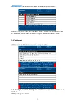
Page 75: ...nd end labels are not set If the start and end labels are set the program between the labels is called 3 Wait input Wait input can make different actions depending on input conditions In the above figure execute the first straight line when there is input or else execute the second straight line Wait input settings are as follows ...

Page 76: ...erent situations 4 File call Note when using file call The starting point set in the file call parameter will offset the called file to the set starting point As shown in the above figure the first file call will go to file number 6 at 0 0 0 and the second will go to file number 6 at 50 50 5 The starting point of the file call setting is similar to the graphic translation operation ...

Page 77: ...nsor signal roughly find the Z highest point home find the X Y midpoint and reset Mode 2 directly find the X Y midpoint find the Z highest point and reset Needlealignment fixed position setting Set the fixed initial scanning position for needlealignment The fixed initial scanning position is generally set in the A point area as shown in the figure below In the figure X and Y indicate the sensing s...

Page 78: ...opy is successful if there is a sound when F1 is pressed Then press F4 to return to the interface of Figure 1 1 Then move by pressing the up down left and right buttons in the lower right corner of the handheld box to select removable disk Press the Enter button to enter the interface of the USB flash drive Press F2 again to paste This will copy the files to the USB flash drive only one file can b...

Page 79: ... exists The controller needs to be restarted after the copy is complete 7 Glue gun offset function In system parameters system parameters set the offset position of the corresponding glue gun and the reference point and then trigger the glue gun offset function by selecting the glue gun command during file editing select the corresponding glue gun and thenapply the offset value and the reference p...

Page 80: ... Whether to use extended IO Whether touse extended input output or both Input outputDIP switch judge the DIPnumber on the hardware The actual object is as follows output is ADT ET102A input is ADT ET202A 232 to 485 is ADT 9143 ADT ET102A Extendedoutput dip switch ...

Page 81: ...User Manual of TV5600 B01 Series Dispensing Control System 81 ADT ET202A ADT 9143 The cable connections of 8849 1600 and ADT 9143 are defined as follows COM0 RS485 MODEBUS Extended input dip switch ...

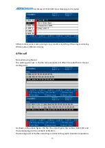
Page 82: ...ized automatic fillet operation for the next corner Eg 1 The track is Start point straight line straight line end point If a custom fillet is added to the corner of 3 the instruction becomes Start point transition arc straight line straight line end point 2 Track Start point straight line arc end point of arc end point If a custom fillet is added to the corner of 4 the instructionbecomes Start poi...

Page 83: ...address the second column allows naming your variable the third column is the value of the variable at the corresponding address Each variable occupies 2 addresses Short integer variable The first column is the corresponding system parameter the user defined short integer variable address the second column allows naming your variable the third column is the value of the variable at the correspondi...

Page 84: ...ns 12 Boot interface logo production You can create a24 bit picturewith 480 272 pixels and a resolution at least 96 with the Brush program of Windows The boot screen is named logo bmp and is placed in the TV5600B01 handheld box disk under the ADT directory 13 Wiping function operation Function Clean and wipe glue gun two modes 1 Wipe wipe glue by XY movement 2 Custom after reaching the position ou...

Page 85: ...his port to determine the wiping mode used initial setting is 1 if the port is configured the custom wipingmodeis used g Auto wipinginterval times The times of processing before the wipingis performed automatically 0 indicate that the process will not automatically trigger wiping h Number of wipingactions The times of action repeatedin XY directionwhen wiping i Wiping in place output time Response...

Page 86: ... it is manually rotated the direction line of the motor may not be connected Please check the line 4 If the motor does not runbut the coordinates of the machining interface have changed it indicates that there is a problem with the motor line Please check the line 5 If the system reset fails please determine if the reset signal exists and whether the high and low levels are set correctly 6 If the ...

Page 87: ...g 25 Too few spline points 132 Alarm input valid 32 X axis exceeds forward travel 133 Update program error 33 Y axis exceeds forward travel 144 Xaxis positive limit 34 Z axis exceeds forward travel 145 Yaxis positive limit 35 A axis exceeds forward travel 146 Zaxis positive limit 36 B axis exceeds forward travel 147 Aaxis positive limit 37 C axis exceeds forward travel 148 Baxis positive limit 40 ...

Page 88: ...vance mode or elsethis value is meaningless 2 End point After XYZ moves to the end point the valve is closed and the Z axis is lifted to the needle height 1 XYZABC coordinates Coordinates of each axis 2 XYZABC enable Whether each axis participates in motion 3 Whether the instruction is executed Whether this programming point processing instruction is executed during processing 4 Use default speed ...

Page 89: ...ault the delay opening time in the file parameter is used or else the time set below is used 7 Delay opening time Use this time when the delay opening mode is in delay mode or else this value is meaningless 8 Advance opening time Use this time when the delay opening mode is in advance mode or else this value is meaningless 9 Default needle height Select Yes to use the needle height in the file par...

Page 90: ...rogramming point processing instruction is executed during processing 4 Use default speed Select Yes to run at the speed set in the file parameter or else use the speed set in speed ratio file parameter 5 Speed ratio This value is meaningful when the default value is not used as above 10 Clockwise ellipse XYZ moves to the specified position in clockwise ellipse arc interpolation It is necessary to...

Page 91: ... enable Whether each axis participates in motion 3 Whether the instruction is executed Whether this programming point processing instruction is executed during processing 4 Use default speed Select Yes to run at the speed set in the file parameter or else use the speed set in speed ratio file parameter 5 Speed ratio This value is meaningful when the default value is not used as above 16 Spline Mov...

Page 92: ...instruction is executed during processing 50 Delay Delay specified time 0 means to suspend processing until the start button is pressed again 1 Delay time The initial delay time of this instruction 2 Whether the instruction is executed Whether this programming point processing instruction is executed during processing 51 Select glue gun Select the specified glue gun for processing 1 Select whether...

Page 93: ...oint processing instruction is executed during processing 224 Program call Call the program between two labels and set the number of calls 1 Whether to call this file Select to callthe file label or else call the following file label 2 Call file number This file number is meaningful when the above option is No 3 Number of calls The number of times the two labels are called directly to execute the ...

Page 94: ...nstruction to the visual dispensing system and works with the end of the matrix First type The number of XY groups is greater than 1 the program will copy the matrix and the MARK point and the CCD shooting instruction will be executed before correctingthe processing points The MARK point corresponding to the first template needs to be set Second type The number of XY groups is less than or equal t...

Page 95: ...erial adapter and its driver Note first turn off the computer s firewall Update steps 1 Connect network port and serial port to the computer and ADT8849 controller Open the serial communication software on the computer and set the baud rate and other parameters on the serial port as follows 2 At power on press the Esc button on the computer keyboard repeatedly until the serial communication softwa...

Page 96: ...ous menu after formatting 4 Press the button 3 and 0 to open the network port as shown below Through the serial port information the IP of this ADT8849 is 192 168 0 64 The following operations are all based on this address In order to enable the network port to communicate with the ADT8849 controller we need to modify the IP of the computer and set the gateway to 192 168 0 1 and the subnet mask to...

Page 97: ...omputer and ADT8849 controller open cmd input ping 192 168 0 64 and test whether it is connected to the glue controller the following picture shows normal state 6 After the network is connected open My Computer on the desktop and enter the corresponding address ftp 192 168 0 64 to show the following screen ...

Page 98: ...der in your client if there is Motion bin and A9Bios bin in the motion folder you need to update the motion algorithm program area and BIOS area and put Motion bin and A9Bios bin in the ADT directory 8 Return to the previous serial port software press the ESC button to enter the previous interface and then press 1 to enter the program update interface the prompt will be as ...

Page 99: ...ing for the update to complete Press 1 to enter the application area and press the Y key on the computer keyboard toupdate the application waiting for the update to complete If there is Motion bin you need to update the motion algorithm program press 2 to enter the motion algorithm program area then press the Y key on the computer keyboard wait for the update to complete then power off and restart...

Page 100: ...eld box and turn on the power Press the Cancel Back button on the handheld box immediately to enter the BIOS interface 4 Use the Up and Down key to select E Program Update and press the Enter key in the upper left 5 Select 1 Update Application and press the Enter key in the upper left to start the update 6 Turn off the power and restart after update 7 View version information Go to Test and select...

Page 101: ...motion library put it in the motion bin file Another folder is named ADT where the handheld box application USERAPP bin is placed Then insert the USB flash drive into the handheld box TV5600 B01 2 Update program Press to enter the system setting interface press Other parameters press to enter the parameter USBflash drive update remote program Press the key system detects the USB flash drive insert...

Page 102: ...ress the number key 3 to update the motion library motion bin only 5 Update all Update all three files above Press the up and down keys select the desired operation press the key the system starts to update the program Restart when the controller update is complete 3 View the program version Press on the handheld box to enter the test interface press again to enter the version information interfac...

Page 103: ...ground 10 Custom 24V Input common 24V power supply 11 Custom 2 Z home GND Internal 24V power ground 3 R home GND Internal 24V power ground GND Internal 24V power ground 12 Start system configuration required 24V Input common 24V power supply 13 Emergency stop allow configurationand modification 4 Xtravel limit 14 Reset allow configurationand modification 5 Ytravel limit 15 Pause system configurati...

Page 104: ...al 24V power ground 10 PE Protective earth Note Multiple 24V and GND terminals on the common input port are convenient for multiple sensor wiring Only one set of 24V and GND need to be connected Note The home port of each axis is configured in Parameter settings Motor features Homeport The above home port wiring uses the default port Note All the above input ports are universal input ports To occu...

Page 105: ...put The INCOM terminal is connected to the positive terminal of the external power supply and the input signal is connected to the corresponding terminal pin The common end of IN0 IN16 is INCOM1 the common end of IN17 IN33 is INCOM2 when used the common end needs to be connected to 24V power supply the input point is low level effective and the current of single input does not exceed 15mA and isn ...

Page 106: ...versal output signal 0 24V Internal 24V power supply 1 Universal output signal 1 24V Internal 24V power supply 2 Universal output signal 2 24V Internal 24V power supply 3 Universal output signal 3 24V Internal 24V power supply 4 Universal output signal 4 EXT_24V EXT_24V EXT_24V EXT_24V EXT_24V EXT_24V J9 CON12 1 2 3 4 5 6 7 8 9 10 11 12 OUT 0 OUT 1 OUT 2 OUT 3 OUT 4 OUT 5 ...

Page 107: ...in 20 of JC1 to the 24V power supply and the output point is low level effective Connect the load between 24V and the output point The internal output circuit has relatively complete protection measures overcurrent protection overvoltage protection short circuit protection overheat protection and freewheeling protection measures but if inductive loads such as relays are connected connect the both ...

Page 108: ...power ground GND 24V power ground VDC 24V power supply VDC 24V power supply PE Earth System X axis AXIS 0 Function A Stepping motor A end A Stepping motor A end B Stepping motor B end B Stepping motor B end System Y axis AXIS 1 Function A Stepping motor A end A Stepping motor A end B Stepping motor B end B Stepping motor B end System Z axis ...

Page 109: ...ply and only one set of VDC and GND needs to be connected 3 02 Four axis closed loop feedback signal input wiring definition EN 0 terminal pin description Wire No Definition Function 1 GND Negative pole ofclosed loop feedback power supply 2 5V Positive pole ofclosed loop feedback power supply 3 EA3 A phase negative pole ofZ axis closed loop feedback signal 4 EA3 A phase positive pole ofZ axis clos...

Page 110: ...ack power supply 2 5V Positive pole ofclosed loop feedback power supply 3 EA4 A phase negative pole ofR axis closed loop feedback signal 4 EA4 A phase positive pole ofR axis closed loop feedback signal 5 EB4 B phase negative pole ofR axis closed loop feedback signal 6 EB4 B phase positive pole ofR axis closed loop feedback signal 7 NC NC 8 NC NC 9 NC NC 10 NC NC EN 2 terminal pin description ...

Page 111: ...pole ofclosed loop feedback power supply 3 EA1 A phase negative pole ofX axis closed loop feedback signal 4 EA1 A phase positive pole ofX axis closed loop feedback signal 5 EB1 B phase negative pole ofX axis closed loop feedback signal 6 EB1 B phase positive pole ofX axis closed loop feedback signal 7 NC NC 8 NC NC 9 NC NC 10 NC NC EN 3 terminal pin description ...

Page 112: ...supply 3 EA2 A phase negative pole ofY axis closed loop feedback signal 4 EA2 A phase positive pole ofY axis closed loop feedback signal 5 EB2 B phase negative pole ofY axis closed loop feedback signal 6 EB2 B phase positive pole ofY axis closed loop feedback signal 7 NC NC 8 NC NC 9 NC NC 10 NC NC 4 ADT HMI and USB UART pin wiring instructions MCD904 HMI Handheld Box Port and RS232 Serial Port ...

Page 113: ...ignal 1 4 HAND_RX1 Controller receives signal 1 5 HAND_RX1 Controller receives signal 1 6 GND_HMI Hand held box power supply ground 7 VCC24V_EXT Handheld box power supply 24V 8 VCC24V_EXT Handheld box power supply 24V 9 NC NC 10 NC Protective earth 11 GND_HMI Hand held box power supply ground 12 GND_HMI Hand held box power supply ground 13 VCC24V_EXT Handheld box power supply 24V 14 NC NC 15 NC NC...

Page 114: ... supply 5V 2 DM Mini USBdifferential signal D 3 DP Mini USBdifferential signal D 4 NC NC 5 GND External power ground 6 M1 Fixed support foot 1 7 M2 Fixed support foot 2 8 M3 Fixed support foot 3 9 M4 Fixed support foot 4 短 差 R178 22Ω USB2 Mini USB M1 6 M2 7 5V 1 DM 2 DP 3 ID 4 0V 5 M3 8 M4 9 R179 22Ω USB_VCC USB_GND USB_GND TVS7 3 1 2 3 1 USB_GND ...

Page 115: ...se 3 IN18 C home or Y servo Z phase 4 IN2 Z home or Z servo Z phase 4 IN19 Bpositive limit 5 IN3 R home or R servo Z phase 5 IN20 Bnegative limit 6 IN4 Xpositive limit 6 IN21 Cpositive limit 7 IN5 Xnegative limit 7 IN22 Cnegative limit 8 IN6 Ypositive limit 8 IN23 Universal input 9 IN7 Ynegative limit 9 IN24 10 IN8 Zpositive limit 10 IN25 11 IN9 Znegative limit 11 IN26 12 IN10 Rpositive limit 12 I...

Page 116: ...and limit ports simply turn the home and limit configuration function of the corresponding axis 2 Input port wiring method Controller internal input port diagram Controller general input connection PV switch V means VCC G means GND O means output The INCOM terminal is connected to the positive terminal of the external power supply and the input signal is connected to the corresponding terminal pin...

Page 117: ...ol System 117 3 ADT 8849 output ports 8849 output ports JCWire No Name Function 1 24VGND Output common 24V ground 2 OUT0 Output0 17 3 OUT1 4 OUT2 5 OUT3 6 OUT4 7 OUT5 8 OUT6 9 OUT7 10 OUT8 11 OUT9 12 OUT10 13 OUT11 14 OUT12 15 OUT13 16 OUT14 17 OUT15 ...

Page 118: ...4V and the output point The internal output circuit has relatively complete protection measures overcurrent protection overvoltage protection short circuit protection overheat protection and freewheeling protection measures but if inductive loads such as relays are connected connect the both ends of the relay coil to freewheeling diodes as shown below Controller internal output structure diagram C...

Page 119: ...CA Supply 5V power externally for X Y axis power supply of common anode connection 2 EXT_VCCB Supply 5V power externally forZ A axis power supply of common anode connection 3 XPU X pulse signal 4 XPU X pulse signal 5 XDR Xdirection signal 6 XDR Xdirection signal 7 YPU Y pulse signal 8 YPU Y pulse signal 9 YDR Ydirection signal 10 YDR Ydirection signal 11 ZPU Z pulse signal 12 ZPU Z pulse signal 13...

Page 120: ...rol System 120 15 APU A pulse signal 16 APU A pulse signal 17 ADR Adirection signal 18 ADR Adirection signal 6 Stepper and servo general wiring diagram 7 Serial port pin wiring instructions 7 01 Serial port 0 wiring definition ADT 8849 8830 COM0 port ...

Page 121: ...ception 4 GND Power ground 5 GND Power ground 6 NC NC 7 VDD5 0 Supply 5V power externally 8 VDD5 0 Supply 5V power externally 9 NC NC 7 02 Serial port 0 and computer wiring ADT 8849 COM0 RS 232communication 7 03 Serial port 1 wiring definition The controller COM1 port is used to connect the handheld box TV5600 B01 ADT 8849 COM1 port Controller PC male connector ...

Page 122: ...2 Wire No Name Function 1 STOP Hard emergency stop signal 2 TX1 Data transmission 3 TX1 Data transmission 4 RX1 Data reception 5 RX1 Data reception 9 13 8 7 NC NC 11 12 6 GND Power ground 14 15 10 VDD5V Supply 5V power externally 8 ADT 8849wiring diagram example ...

Page 123: ...User Manual of TV5600 B01 Series Dispensing Control System 123 ...

Page 124: ...User Manual of TV5600 B01 Series Dispensing Control System 124 Appendix VIII AMC1600P Wiring Instructions 1 AMC 1600 input ports ...

Page 125: ...niversal input 5 IN28 Universal input 6 IN5 Xnegative limit 6 IN17 B home 6 IN29 Universal input 7 IN6 Ypositive limit 7 IN18 C home 7 IN30 Universal input 8 IN7 Ynegative limit 8 IN19 Bpositive limit 8 IN31 Universal input 9 IN8 Zpositive limit 9 IN20 Bnegative limit 9 IN32 Universal input 10 IN9 Znegative limit 10 IN21 Cpositive limit 10 IN33 Universal input 11 IN10 Rpositive limit 11 IN22 Cnega...

Page 126: ...r general input connection PV switch V means VCC G means GND O means output The INCOM terminal is connected to the positive terminal of the external power supply and the input signal is connected to the corresponding terminal pin The common end of IN0 IN16 is INCOM1 the common end of IN17 IN33 is INCOM2 when used the common end needs to be connected to 24V power supply the input point is low level...

Page 127: ...X_24VAGND External 24V power ground 4 Output port wiring method The switching output of this control system is the open collector output The common terminal is the first pin of JC1 which is also the GND of the load power supply When using please connect the pin 20 of JC1 to the 24V power supply and the output point is low level effective Connect the load between 24V and the output point The intern...

Page 128: ...ler output port general wiring Note The recommended power supply voltage is 24V preferably not more than 30V The positive and negative poles must not be reversed and the load should not be short circuited or else it will cause accidents 5 AMC1600P motor driver interface definition AMC 1600 motor driver interface or ...

Page 129: ...ential connection method and common anode connection method which are determined by the type of the encoder The encoder output usually has open collector output complementary output voltage output and long line driver output The open collector output complementary output and voltage output can adopt the common anode connection method and the long line driver output adopts the differential connecti...

Page 130: ...age is determined by the encoder When using a 5V power supply the resistor R isn t required When using a 12V power supply R can be 1K 2K resistor When using a 24V power supply R can be 2K 5K resistor Note Try to use the differential output encoder because the differential method is better in anti interference when the line is long 7 Stepping and servo general wiring diagram Encoder grating ruler E...

Page 131: ...User Manual of TV5600 B01 Series Dispensing Control System 131 8 AMC1600serial port AMC1600 COM1 port ...

Page 132: ...ame Function 1 STOP STOP 2 TX1 Data transmission 3 TX1 Data transmission 4 RX1 Data reception 5 RX1 Data reception 9 NC NC 11 12 6 GND Power ground 14 15 10 VDD5V Supply 5V power externally 13 8 7 VDD24V Supply 24V power externally 9 Analog definition AMC 1600analog output ...

Page 133: ...5600 B01 Series Dispensing Control System 133 1 DAOUT1 Analog voltage line 1 2 GND Analog voltage reference ground 3 DAOUT2 Analog voltage line 2 4 GND Analog voltage reference ground 10 AMC 1600 wiring diagram example ...

Reviews: