


4-Channel Digital Video Recorder
23
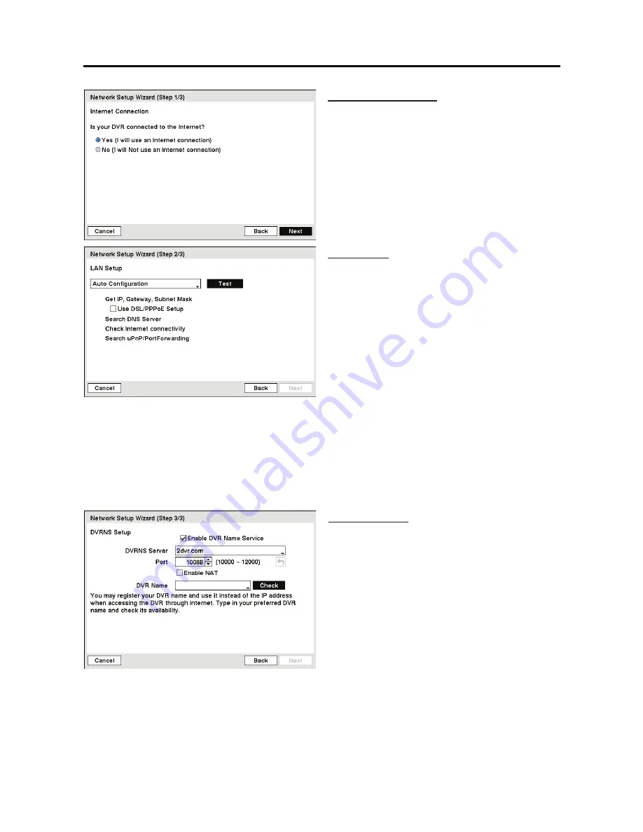
Internet Connection
Select whether or not your DVR is connected
to the Internet.
LAN Setup
Select between
Auto Configuration
and
Manual
Configuration
for network configuration, and
then select the
Test
button to test the network
configuration you selected.
NOTE: Selecting
Auto Configuration
allows
the DVR to automatically obtain LAN
parameters (IP address, Gateway, Subnet
Mask and DNS Server address). Selecting
Manual Configuration
allows you to set up
LAN parameters manually.
NOTE: The network configuration you set should be tested by selecting
Test
, otherwise
the
Next
button will cannot be selected, and you cannot move to the next step.
y
Use DSL/PPPoE Setup:
Selecting the box allows you to set up the DSL network. Entering
the ID and password for DSL connection is required.
NOTE: When the error message “No Device supporting UPnP” displays, check the NAT
device supports the UPnP Port Forwarding function and the function is set to enabled.
DVRNS Setup
y
Use DVR Name Service:
Select the box to
use the DVR Name Service.
y
DVRNS Server:
Enter the IP address or
domain name of the DVRNS server.
y
Port:
Set the port number of the DVRNS
server.
y
Enable NAT:
Select the box when using the
NAT (Network Address Translation) device.
y
DVR Name:
Enter the DVR name to be
registered on the DVRNS server.
y
Check:
Select the box to check whether or
not the name you entered can be used.
NOTE: The DVR name you entered should be checked by selecting
Check
, otherwise the
DVRNS changes will not be saved.
NOTE: When entering no name or a name already registered on the DVRNS server, an error
message displays.
Summary of Contents for 4-channel DVR
Page 1: ......
Page 2: ......
Page 68: ...User s Manual 60...
Page 77: ...4 Channel Digital Video Recorder 69 Map of Screens...


