background image


Industrial PCs MCR5000


36 

© ads-tec GmbH • Raiffeisenstr.14 • 70771 Leinfelden-Echterdingen


3)


Remove the installation adapter from the MCR 5000 device. 


B

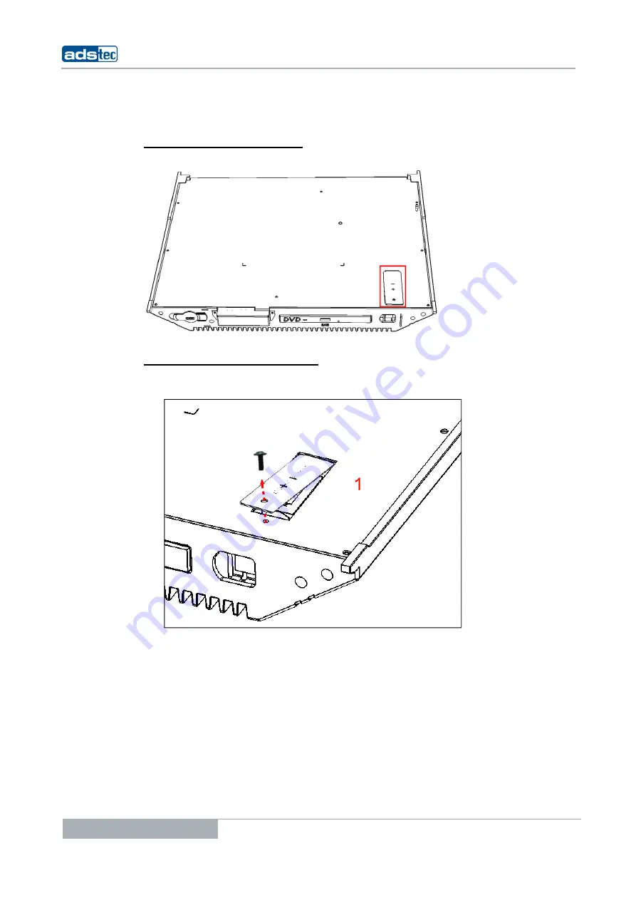
ATTERY COMPARTMENT LOCATION


The location of the battery compartment is highlighted in the figure. 


O

PENING THE BATTERY COMPARTMENT


1)


Remove the safety screw from the battery compartment 


lid by using a suitable screw driver. 


Summary of Contents for MCR5000

Page 1: ...User Manual Industrial PCs MCR5000 Version 1 3...

Page 2: ...Industrial PCs MCR5000 2 ads tec GmbH Raiffeisenstr 14 70771 Leinfelden Echterdingen Product Portfolio Copyright ads tec GmbH Raiffeisenstr 14 D 70771 Leinfelden Echterdingen Germany...

Page 3: ...1 2 5 SAFETY INSTRUCTIONS 11 3 ASSEMBLY 12 3 1 OVERALL DEVICE DIMENSIONS 12 3 2 ORDER OF INSTALLATION 13 4 COMMISSIONING 23 4 1 AVAILABLE INTERFACES 23 4 2 CABLE INSTALLATION 24 4 3 READINESS FOR OPER...

Page 4: ...Cs MCR5000 4 ads tec GmbH Raiffeisenstr 14 70771 Leinfelden Echterdingen 7 2 GENERAL DATA 33 8 SERVICE AND SUPPORT 34 8 1 ADS TEC SUPPORT 34 8 2 COMPANY ADDRESS 34 9 BATTERY REPLACEMENT 35 10 FUSE REP...

Page 5: ...o Echterdingen S chterdingen 45894 0 45894 990 des large enterprises and globally active corporat ate know how and comprehensive services in t ocessing technology and systems engineering ements full a...

Page 6: ...re optimised and or zero defect operations It also precedes tips and suggestions for efficient unit implementation and software optimisation 1 3 DATA IMAGES AMENDMENTS AND VARIATIONS The texts data an...

Page 7: ...1 6 ENVIRONMENTAL CONDITIONS The device may be operated under the following conditions Failure to observe these specifications will terminate any warranty for this device Ads tec cannot be held liabl...

Page 8: ...N EN 60950 1 2001 VDE0805 IEC950 Safety of Information Technology Equipment The device meets the DIN EN 60068 2 6 test requirements sinus excitation The device meets the DIN EN 60068 2 27 test require...

Page 9: ...mponents are contained in the packaging 1 x MCR 5000 1 x Installation bracket pre installed 1 x Locking plate pre installed 1 x Set of keys for locking plate lock The optional cable set might include...

Page 10: ...ed in particular The manual contains the most important instructions on how to use this device in a safe way Appropriate storage proper transport installation and commissioning as well as careful oper...

Page 11: ...heat them up over 100 C dispose of them properly and protect lithium batteries from direct sun light humidity and condensation Lithium batteries may only be replaced by the same type or by a type rec...

Page 12: ...Industrial PCs MCR5000 12 ads tec GmbH Raiffeisenstr 14 70771 Leinfelden Echterdingen 3 ASSEMBLY 3 1 OVERALL DEVICE DIMENSIONS...

Page 13: ...0 with DV Observe the Note The maximum torq installation Tighten Echterdingen ON be checked before starting the installation bearing capacity of the wall ermitted for fixing with M6 screws by VESA 10...

Page 14: ...000 can be fixed to the display the respective brackets or retainers for protecting the MCR 5000 from falling must be in place The fall protection measures must correspond to the BGV C1 regulations Re...

Page 15: ...LE FOR INSTALLING THE MCR 5000 TO A WOODEN WALL FROM 18 MM PLYWOOD Required installation materials not included in the scope of delivery 6 units of M6 x 35 Allen screw acc to DIN 912 6 units of M6 was...

Page 16: ...the installation This is done by opening the lock and by removing the locking plate upwards REMOVING THE INSTALLATION BRACKET For removing the installation bracket it is required to unhinge the previ...

Page 17: ...luding 6 x M6 screws must be screwed to the monitor according to the instructions of the monitor manufacturer Horizontal installation Warning All six screws must be used for fixing the installation br...

Page 18: ...use and the installation conditions at the display For this purpose the monitor has to be installed in a tilted position according to the manufacturer instructions Vertical installation Warning The i...

Page 19: ...t be carried out by at least 3 persons due to the weight of the equipment Fix the monitor to the MCR 5000 device by using the pre installed installation bracket Note The figure shows the installation...

Page 20: ...0 20 ads tec GmbH Raiffeisenstr 14 70771 Leinfelden Echterdingen Subsequently the monitor must be pushed beyond the retainer lobes Make sure that the installation bracket is flush with the MCR 5000 un...

Page 21: ...elden Echterdingen 21 SECURING MONITOR AND MCR 5000 The installation bracket is screwed to the MCR 5000 case by using the previously removed fixing screws M6x10mm Warning The monitor must still be sup...

Page 22: ...he monitor Warning You finally have to check that the monitor is properly installed this can be done by visual inspection and by carefully trying to pull the monitor to the front at the bottom edge Th...

Page 23: ...ce may only be switched on after the required ambient temperature is reached in order to avoid condensate accumulation Make sure to meet the permissible voltage requirements for this device Warning Af...

Page 24: ...pushing the Power button 1 Subsequently turn the device on by using the ATX button 2 4 3 READINESS FOR OPERATION CHECKS Accurately check the unit for any hidden damages possibly incurred during improp...

Page 25: ...MCR 5000 device is equipped with an AC OUT socket which allows supplying external devices If the MCR 5000 is attached to a monitor the monitor can also be supplied through the AC OUT socket of the MC...

Page 26: ...using the Lock USB software tool You ll find the software and the documentation on the service CD TOP USB INTERFACE One USB interface can be accessed from the front The interface is located under a p...

Page 27: ...h the IEEE 1394a standard FireWire 400 5 5 NETWORK CONNECTION RJ45 If the drivers required for functioning are installed on the device the control system may be integrated in an Ethernet network suppo...

Page 28: ...om ads tec including wireless LAN are equipped with a Mini PCI WLAN card including Atheros chips If a device is delivered including operating system by ads tec all required device drivers will also be...

Page 29: ...ng a digital monitor VGA monitors A adapter DVI I single link interface Signals are transmitte SIGNAL NAME TMDS Data2 TMDS Data2 TMDS Data2 4 Shield N C N C DDC Clock SCL DDC Data SDA Analogue vertica...

Page 30: ...commercially available cinch cable The Audio L R cinch input jack allows transmitting analogue audio signals to other pieces of equipment The input jacks may be connected with commercially available c...

Page 31: ...rmatted in NTFS format default for Windows XP Warning Never remove or insert a hard disk during operation when the device is powered 6 2 DVD DRIVE INTEGRATED MODEL NOTEBOOK The DVD drive is located be...

Page 32: ...drive for removable media is integrated in the device by default Additionally the system provides USB interfaces to which an external drive could be connected Warning Removing an external drive during...

Page 33: ...cinch socket sound output via four internal speakers Removable disk drives As an option Integrated slim line DVD drive Network 1 x Ethernet 10 100 1000 Mbit RJ45 Wireless As an option WLAN card incl 2...

Page 34: ...supplier in question as ads tec will not be able to reply to such questions ads tec does not provide support services for any device or unit that was not bought directly from ads tec In any such case...

Page 35: ...THE LOCKING PLATE Open the locking plate by using the supplied set of keys After that the locking plate can completely be unhinged and removed REMOVING THE INSTALLATION BRACKET 1 Remove both safety sc...

Page 36: ...en 3 Remove the installation adapter from the MCR 5000 device BATTERY COMPARTMENT LOCATION The location of the battery compartment is highlighted in the figure OPENING THE BATTERY COMPARTMENT 1 Remove...

Page 37: ...driver REPLACING THE BATTERY 3 Now the lithium battery can be removed It must be replaced by the same battery type only The type of battery to be used is Saft LS 14250 1 2AA 3 6V 1000mAh Lithium batt...

Page 38: ...5000 device Place the retaining clip on top of the newly inserted battery first Subsequently fit the screws to the battery compartment and to the MCR 5000 casing Observe the required security measure...

Page 39: ...FUSE The MCR 5000 fuse is located in the position highlighted in the picture REMOVING THE FUSE In order to remove the fuse inside the MCR 5000 device please push a suitable tool e g a screw driver int...

Page 40: ...of steps in this description for re installing the fuse Push the fuse into the retainer and push both components together back into the unit Activate the locking mechanism by using a suitable tool scr...

Reviews: