


ii
Table of Contents
A Specifications.................................................................... 21
General .............................................................................. 21
Power Supply..................................................................... 21
System Monitoring ............................................................. 22
Cooling System.................................................................. 22
Physical.............................................................................. 23
Operating Environment ...................................................... 23
Backplane .......................................................................... 23
Shock and Vibration........................................................... 23
Safety and EMC/EMI Compliance ..................................... 23
B Backplane Drawing and Pin Assignments ..................... 25
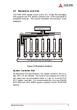
Backplane Layout .............................................................. 25
Pin Assignments ...................................................... 27
PXI Connectors Pin Assignments ................................. 27
Bus Segments and Interrupt Routings ............................... 33
Bus Segments and Interrupt Routings ............................... 34
Miscellaneous Connectors Pin Assignments ..................... 35
CN1, CN7, CN8, CN9: ATX-like DC Power
input connectors ................................................. 35
PCI VIO Selection Screw Terminals ............................. 35
J6 INH#: DC power inhibit signal .................................. 36
J8 RST#: System reset signal ...................................... 36
J9 FAL#: Power supply fail input .................................. 36
J5: Connector for LED power status ............................. 36
CN5: SMB (System Management Bus) connector ...... 37
JP1: 10 MHz Reference Clock ...................................... 37
J2: POWER SENSE ..................................................... 37
Important Safety Instructions............................................... 39
Warranty Policy ..................................................................... 41
Summary of Contents for PXIS-3320
Page 4: ......
Page 12: ...4 Introduction...
Page 20: ...12 Chassis Overview...
Page 32: ...24 Specifications...
Page 34: ...26 Backplane Drawing and Pin Assignments Figure B 2 CBX 6015 rear view...


