


Backplane Drawing and Pin Assignments
35
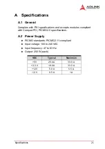
B.5 Miscellaneous Connectors Pin Assignments
CN1, CN7, CN8, CN9: ATX-like DC Power input connectors
NOTE
Pin #8, #9, and #18 are not standard ATX power defini-
tions.
PCI VIO Selection Screw Terminals
NOTE
The V(I/O) must be shorted to 3.3V or +5V. The
default factory setting is to short V(I/O) to +5V.J1 INH#:
DC power inhibit signa.
Signal Name
Pin #
Pin #
Signal Name
V2SENSE
1
11
V2 (+3.3V)
V2 (+3.3V)
2
12
V4 (-12V)
GND
3
13
GND
V1 (+5V)
4
14
INH#
GND 5
15
GND
V1 (+5V)
6
16
SRTN
GND
7
17
GND
FAL#1
8*
18*
V3(+12V)SENSE
DEG#1
9*
19
V1(+5V) SENSE
Position
Signal Name
J1
+5V
J3
V(I/O)
J4
+3.3V
J7
GND
J10
-12V
J11
+12V
Summary of Contents for PXIS-3320
Page 4: ......
Page 12: ...4 Introduction...
Page 20: ...12 Chassis Overview...
Page 32: ...24 Specifications...
Page 34: ...26 Backplane Drawing and Pin Assignments Figure B 2 CBX 6015 rear view...


