30
Getting Started
5.2
PMC/XMC Module Installation
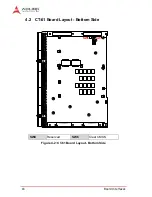
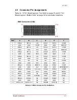
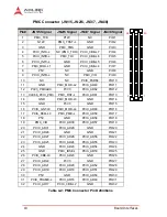
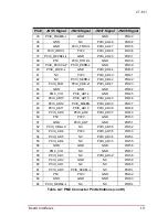
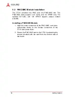
The CT-61 provides one PMC and one PMC/XMC slot. The
PMC/XMC slots support 3.3V V(I/O) and 5V VPWR only. For
optional 5V V(I/O) and 12V VPWR support, please contact
ADLINK.
Installing a PMC/XMC Module
1. Align the male connectors of the PMC/XMC card (com-
ponent-side down) to the female connectors of the
CT-61 and press down.
2. Secure the PMC/XMC card to the CT-61 by attaching the
screws provided with the card from the bottom side of
the board.
Summary of Contents for CT-61
Page 8: ...viii List of Tables This page intentionally left blank ...
Page 10: ...x List of Figures This page intentionally left blank ...
Page 20: ...10 Specifications This page intentionally left blank ...
Page 38: ...28 Board Interfaces This page intentionally left blank ...
Page 42: ...32 Driver Installation This page intentionally left blank ...
Page 52: ...42 Utilities This page intentionally left blank ...
Page 64: ...54 BIOS Setup Utility PC Health Configuration ...
Page 74: ...64 BIOS Setup Utility This page intentionally left blank ...

