52
Getting Started
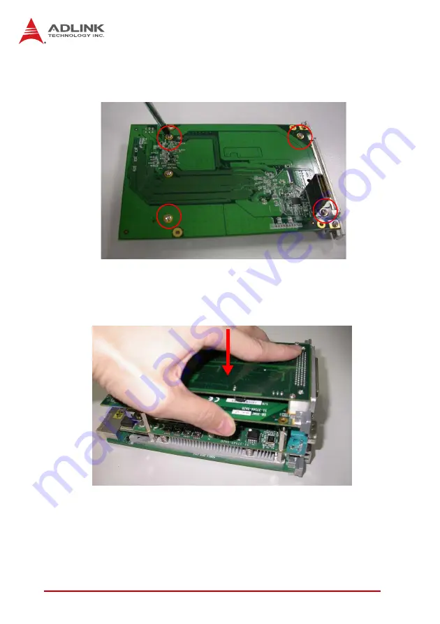
5. Secure the PMC/XMC card to the DB-3UMC by attach-
ing four screws (provided with the card) from the under-
side of the daughter board.
6. Align the male board-to-board connector (CN1) of the
PMC/XMC assembly to the female board to board con-
nector (CN7) of the DB-3610L2 riser card and press
down.
Summary of Contents for cPCI-3610 Series
Page 6: ...vi Preface This page intentionally left blank ...
Page 10: ...x Table of Contents This page intentionally left blank ...
Page 12: ...xii List of Figures This page intentionally left blank ...
Page 14: ...xiv List of Tables This page intentionally left blank ...
Page 20: ...6 Introduction This page intentionally left blank ...
Page 26: ...12 Specifications This page intentionally left blank ...
Page 32: ...18 Functional Description This page intentionally left blank ...
Page 60: ...46 Board Interfaces This page intentionally left blank ...
Page 70: ...56 Getting Started This page intentionally left blank ...
Page 72: ...58 Driver Installation This page intentionally left blank ...
Page 104: ...90 BIOS Setup This page intentionally left blank ...


