background image

nanoX-BASE 

User’s Manual

Page  16

6.5

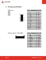
PCI Express and SDVO Slots

PCI Express x1
PCIE1
PCIE2
PCIE3
PCIE6

Pin

Signal

Pin

Signal

B1

+ 12V

A1

NC

B2

+ 12V

A2

+ 12V

B3

NC

A3

+ 12V

B4

GND

A4

GND

B5

SMB_CK

A5

TCK

B6

SMB_DAT

A6

TDI

B7

GND

A7

NC

B8

+ 3.3V

A8

TMS

B9

TRST#

A9

+ 3.3V

B10 +3.3VSB

A10 + 3.3V

B11 WAKE#

A11 PERST#

B12 NC

A12 GND

B13 GND

A13 

B14 PETp0

A14 REFCLK-

B15 PETn0

A15 GND

B16 GND

A16 PERp0

B17 NC

A17 PERn0

B18 GND

A18 GND

A1

A11
A12

A18

B1

B11
B12

B18

PCI Express Mini Card - PCIE4 (USB6)

Pin

Signal

Pin

Signal

1

GND

14

+3.3V

2

USBD-

15

+3.3V

3

USBD+

16

CLKREQ#

4

CPUSB#

17

CPPE#

5

RESERVED

18

REFCLK-

6

RESERVED

19

7

SMB_CK

20

GND

8

SMB_DAT

21

PERn0

9

+1.5V

22

PERp0

10

+1.5V

23

GND

11

WAKE#

24

PETn0

12

+3.3VSB

25

PETp0

13

PERST#

26

GND

26

1

Summary of Contents for COM Express nanoX-BASE

Page 1: ...nanoX BASE User s Manual Manual Revision 2 02 Revision Date September 2 2013 Part Number 50 1J030 1020...

Page 2: ...er s Manual Page 2 Revision History Release Date Change 2 00 2010 10 19 Intial Release 2 01 2012 07 11 Add COM 0 R2 0 Type 10 module support PCB rev A2 2 02 2013 09 02 Correct USB Client connector des...

Page 3: ...cation 10 4 Function Block Diagram 11 5 Mechanical Dimensions 12 6 Connectors and Pinouts 13 6 1 Carrier Board Signals 13 6 2 Connector and Pinout Compatibility 13 6 3 Carrier Board Design 13 6 4 COM...

Page 4: ...Power Connectors 32 6 24 Power Jumper Settings 33 6 25 Other Jumper Settings 34 7 Secondary BIOS 35 7 1 FWH Secondary BIOS COM 0 Rev 1 0 35 7 2 SPI Secondary BIOS COM 0 Rev 2 0 36 8 Switches LEDs Pow...

Page 5: ...mages Environmental Responsibility ADLINK is committed to fulfill its social responsibility to global environmental preservation through compliance with the European Union s Restriction of Hazardous S...

Page 6: ...d instructions properly Additional information aids and tips that help users perform tasks Information to prevent minor physical injury component damage data loss and or program corruption when trying...

Page 7: ...EM board The nanoX BASE is a standard ATX size carrier board Together with the COM Express module of your choice and off the shelf add on cards you can quickly emulate the functionality of your desire...

Page 8: ...ton and packing materials for inspection Obtain authorization from the dealer before returning any product to ADLINK f nanoX BASE Reference Carrier Board f SDVO flat cable f 7 pin SATA cable f 4 pin M...

Page 9: ...terface SPI for COM 0 Rev 2 0 modules Selection of active BIOS can be made by jumper setting See Chapter 7 Secondary BIOS 2 3 Onboard Audio The nanoX BASE is equipped with a Realtek ALC888 audio codec...

Page 10: ...CN6 CN1 CN21 CN15 CN12 JPX1 JP1 JPY7 JP18 CN31 Winbond W83627DHG P ALC 883 CN28 nanoX BASE 51 77102 0A20 PCI1 JP9 JP19 CN38 CN39 S1 1 2 3 4 ON DIP CN18 JP16 JP17 JP15 CN34 LED4 LED3 LED2 LED1 SW3 SW4...

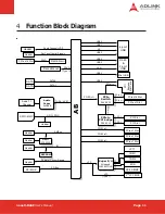
Page 11: ...e x1 PCIe x1 PCIE0 x1 PCIe x1 PCIe x16 Slot PCIe x1 PCIe x1 Slot PCI Slot PCI Slot PCI PCI PCIE1 x1 PCIe x1 Slot PCIE2 x1 PCIe x1 Slot PCIE3 x1 PCIe x1 Slot LPC LPT1 Single Channel LVDS Header SATA0 S...

Page 12: ...nanoX BASE User s Manual Page 12 5 Mechanical Dimensions All tolerances 0 05 mm Other tolerances 0 2 mm...

Page 13: ...e CDG Please note that the CDG gives design advice and contains unverified reference schematics The nanoX BASE design and schematics are fully verified and we recommend that you follow them as a refer...

Page 14: ...D FIXED B21 GND FIXED A22 SATA2_TX B22 SATA3_TX A22 RSVD B22 RSVD A23 SATA2_TX B23 SATA3_TX A23 RSVD B23 RSVD A24 SUS_S5 B24 PWR_OK A24 SUS_S5 B24 PWR_OK A25 SATA2_RX B25 SATA3_RX A25 RSVD B25 RSVD A2...

Page 15: ...79 LVDS_BKLT_EN A80 GND FIXED B80 GND FIXED A80 GND FIXED B80 GND FIXED A81 LVDS_A_CK B81 LVDS_B_CK A81 LVDS_A_CK B81 DD10_PAIR3 A82 LVDS_A_CK B82 LVDS_B_CK A82 LVDS_A_CK B82 DD10_PAIR3 A83 LVDS_I2C_C...

Page 16: ...SB A10 3 3V B11 WAKE A11 PERST B12 NC A12 GND B13 GND A13 REFCLK B14 PETp0 A14 REFCLK B15 PETn0 A15 GND B16 GND A16 PERp0 B17 NC A17 PERn0 B18 GND A18 GND A1 A11 A12 A18 B1 B11 B12 B18 PCI Express Min...

Page 17: ...B32 NC A32 NC B33 NC A33 NC B34 NC A34 NC B35 NC A35 NC B36 NC A36 NC B37 NC A37 NC B38 NC A38 NC B39 NC A39 NC B40 NC A40 NC B41 NC A41 NC Pin Signal Pin Signal B42 NC A42 NC B43 NC A43 NC B44 NC A44...

Page 18: ...rose FH12 30S 0 5SH 55 30 pin FFC FPC connector on the module Connect the SDVO signal from the output connector on the Type 1 module to CN30 on the nanoX BASE carrier board using the flat ribbon cable...

Page 19: ..._RED A33 NC B34 SDVOC_RED A34 GND B35 GND A35 RSVD B36 GND A36 RSVD B37 SDVOC_GRN A37 GND B38 SDVOC_GRN A38 GND B39 GND A39 RSVD B40 GND A40 RSVD B41 SDVOC_BLU A41 GND Pin Signal Pin Signal B42 SDVOC_...

Page 20: ...gnal B Signal 32 AD 16 32 AD 17 33 3 3V 33 C BE 2 _L 34 FRAME_L 34 Ground 35 Ground 35 IRDY_L 36 TRDY_L 36 3 3V 37 Ground 37 DEVSEL_L 38 STOP_L 38 Ground 39 3 3V 39 LOCK_L 40 Reserved 40 PERR_L 41 Res...

Page 21: ...LPC_FRAME L 7 LPC_AD0 5 CLK_DEBUG 6 GND 1 10 5 6 CN35 LPC Debug Header 6 8 SD Card Slot Pin Signal 9 SD_DAT2 1 SD_DAT3 2 SD_CMD 3 GND 4 3 3V 5 SD_CLK 6 GND 7 SD_DAT0 8 SD_DAT1 See 6 21 GPIO S1 for in...

Page 22: ...ress Selection Jumpers JP15 to JP17 configure the device address of the Atmel AT24C08A I2C EEPROM The 8K AT24C08A EEPROM only uses the A2 device address bit See the device datasheet for detailed infor...

Page 23: ...3 BI_DB 4 BI_DC 5 BI_DC 6 BI_DB 7 BI_DD 8 BI_DD Pin Signal 1 5V 2 USB 3 USB 4 Ground CN13 Mini USB USB Client This connector supports USB client functionality using the Intel SCH USB Port 2 interface...

Page 24: ...RANGE Center Subwoofer BLACK Rear Speaker Out GRAY Side Speaker Out CN23 Audio Pin Header Pin Signal Pin Signal 1 MIC In L 2 AGND 3 MIC In R 4 ACZ Detect 5 Line In R 6 MIC In Detect 7 Front I O Sense...

Page 25: ...LVDS_A3 20 GND 21 NC 22 NC 23 GND 24 NC 25 NC 26 GND 27 NC 28 NC 29 GND 30 NC 31 NC 32 NC 33 NC 34 NC CNY6 LVDS Flat Panel Connector Pin Signal Pin Signal 1 GND 2 Panel PWR 3 Backlight CTRL 4 GND 5 B...

Page 26: ...ness Control CN7 pin 3 Backlight CTRL to Voltage Level or PWM When set to Voltage Level the Backlight CTRL signal can be varied from 0 5V in 0 5V increments Jumper Status 1 2 Voltage Level 2 3 PWM 1 2...

Page 27: ...nanoX BASE Pin Signal Pin Signal 6 DSR 1 DCD 7 RTS 2 RXD 8 CTS 3 TXD 9 RI 4 DTR 5 GND CN20 IrDA Connector From Super I O on nanoX BASE Pin Signal 1 5V 2 No connect 3 IrRXD 4 Ground 5 IrTXD 1 CNX1 2 CO...

Page 28: ...15 ERROR 3 DATA1 16 INIT 4 DATA2 17 SELIN 5 DATA3 18 GND 6 DATA4 19 GND 7 DATA5 20 GND 8 DATA6 21 GND 9 DATA7 22 GND 10 ACK 23 GND 11 BUSY 24 GND 12 PAPER EMPTY 25 GND 13 SEL 26 N C 2 1 3 6 5 4 Keybo...

Page 29: ...gnal Pin Signal 1 SMB_CLK 2 SMB_DAT 3 PWRBTN 4 BATLOW 5 PS_ON 6 3 3V 7 12V 8 5V 9 SMB_ALERT 10 NC 6 19 Smart Battery Management FN1 3 12 Volt Fan Connector Pin Signal 1 GND 2 12V 3 FAN_SEN 4 FAN_PWM C...

Page 30: ...2 Low High GPIO address A1 3 Low High GPIO address A2 4 Enabled Disabled SD card enable 6 21 GPIO 1 2 3 4 ON DIP CN39 Module GPIO GPIOs of CN39 come from the COM Express module Pin Signal Pin Signal...

Page 31: ...I_M66EN 31 BATLOW 32 WAKE1 33 PEG_ENABLE 34 PEG_LANE_RV 35 KBINH 36 SYS_RESET 37 GND 38 GND 39 PWBTN 40 PWR_OK 1 2 39 40 Pin Signal Pin Signal 1 Power LED 11 BUZZER 2 WDT_LED 12 NC 3 GND 13 NC 4 NC 14...

Page 32: ...power for the COM Express module is provided by the ATX 12V 4 pin connector The system will not power up if CN41 is not connected to the power supply 1 2 3 4 5 6 7 8 9 10 11 12 3 3 V 3 3 V Ground 5 V...

Page 33: ...ithout P5V 2 3 AT with P5V 1 2 3 JP21 PS_ON Signal Source Jumper Status 1 2 SUS_S3 2 3 SUS_S5 All ADLINK modules support S3 mode and use the SUS_S3 signal to control the PS_ON signal which is used to...

Page 34: ...tatus 1 2 4EH 2 3 2EH 1 2 3 JP10 Super IO Enables disables the Super IO Jumper Status 1 2 Enable 2 3 Disable JP9 Keyboard Controller Function Enables disables the Keyboard Controller on the Super I O...

Page 35: ...OS solutions can be used as an alternative to the on module BIOS and provide support for the following f Testing new BIOS versions f Development of firmware modifications f Recovery if soldered BIOS o...

Page 36: ...y BIOS When using SPI Secondary BIOS the FWH BIOS chip must be removed from the carrier board If the FWH BIOS chip is not removed the COM Express module may not boot correctly To use the BIOS on the m...

Page 37: ...his switch can be used to power up and power down the system with an ATX power supply The SW2 switch is the Reset Button SW1 SW2 At the top of the board below the SATA connectors are two more switches...

Page 38: ...ebugging There are two LEDs that display the actual POST data 8 3 Information LEDs A row of mini LEDs to the left of the POST display indicates the following LED1 HDD SATA hard disk activity LED2 5Vsb...

Page 39: ...e The system will not power on unless an ATX 12V 4 pin connector is connected If your power supply has a 24 pin ATX connector then attach the connectors as shown If your power supply has a 20 pin ATX...

Page 40: ...erate the system in AT Mode with an ATX power supply use the AT mode PSU converter cable no 5Vsb to connect the ATX 20 24 pin power connector to the carrier board as shown Set the ATX AT Mode jumper J...

Page 41: ...voltage and power source settings Always install and operate equipment near an easily accessible electrical socket outlet Secure the power cord do not place any object on over the power cord Only ins...

Page 42: ...3 300 Fang Chun Rd Zhangjiang Hi Tech Park Pudong New Area Shanghai 201203 China Tel 86 21 5132 8988 Fax 86 21 5132 3588 Email market adlinktech com ADLINK Technology Beijing Address 1 E 801 100085 Rm...

Page 43: ...2 Seocho Dong Seocho Gu Seoul 137 070 Korea Tel 82 2 2057 0565 Fax 82 2 2057 0563 Email korea adlinktech com ADLINK Technology Singapore Pte Ltd Address 84 Genting Lane 07 02A Cityneon Design Centre S...

Page 44: ......

Reviews: