Page 13
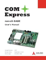
nanoX-BASE
User’s Manual
6
Connectors and Pinouts
6.1
Carrier Board Signals
6.2
Connector and Pinout Compatibility
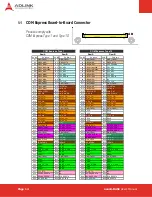
Connectors positions and pinouts comply with pinout and signal descriptions in the “COM.0 -
COM Express Module Base Specification”. This document includes descriptions of pinouts, signal
descriptions and mechanical characteristics of the COM Express specification. The nanoX-BASE
is compliant with COM Express
Mini form factor, Type 1 and Type 10 modules
.
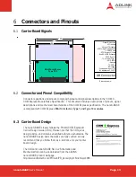
6.3 Carrier Board Design
The nanoX-BASE closely follows the PICMG COM Express®
Carrier Design Guide (CDG). Please note that the CDG gives
design advice, and contains unverified reference schematics. The
nanoX-BASE design and schematics are fully verified, and we
recommend that you follow them as a reference for your carrier
board design.
The CDG and nanoX-BASE Rev. A2 Schematics and
Mechanical files can be downloaded from the ADLINK
nanoX-BASE product webpage:
http://www.adlinktech.com/PD/web/PD_detail.php?cKind=&pid=986
55
.
84
.
AB
.
95
.
.
125
.
95
Dimensions in mm
- Gigabit Ethernet port
- LPC interface
- 4 Serial ATA channels
- AC'97 or High Definition Audio
- 6 USB 2.0 ports
- 6 PCI Express x1 Lanes
- Dual 24-bit LVDS channels
- SDVO (Type 10)
- TV-out, VGA (Type 1)
- GPIO / SDIO
- Keyboard
- I
2
C / SMBus
-SPI support
- Primary power input: +12V,
+5V standby and 3.3V RTC
AB Connector
Mini Form Factor
Type 1/10
Summary of Contents for COM Express nanoX-BASE
Page 44: ......

