


APDCAM User’s Guide
Page 12/32
3. APDCAM Reference Manual
In this section a detailed description is given of the APDCAM system.
3.1. System
Overview
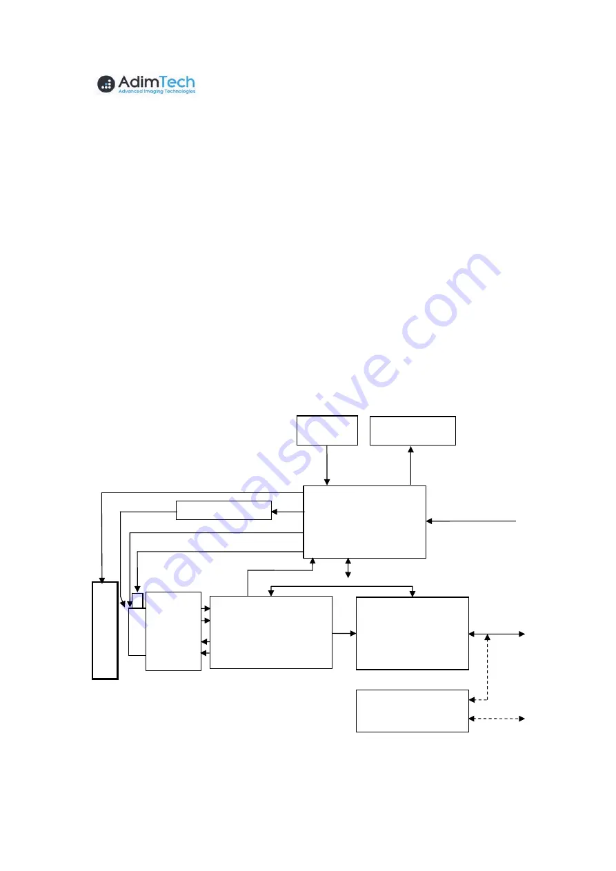
The block scheme of APDCAM is shown in
Figure 4.
The APD array detector is
mounted on a copper tab which can be cooled/heated by a Peltier element. This way the
temperature of the detector is stabilised at a reference value which can be somewhat (max
~15 C) below or above the ambient temperature. Cooling the detector does not offer ad-
vantages in terms of noise, therefore the temperature control is provided only to stabilise
the gain. A shutter is mounted in front of the detector so that it can be coupled off from
the input light and can be calibrated using the calibration light. The DC current of the
calibration LED is set digitally while the light is coupled to the detector via four optical
fibres which illuminate the detector from 4 directions. The detector bias voltage is also
controlled digitally thus having the possibility of adjusting the detector gain to the re-
quirements.
The photocurrent from each of the 32 detector pixels is amplified by a sensitive low
noise amplifier. To compensate for the offset drift the output offset level of the amplifiers
can be controlled digitally through 32 Digital to Analog Converters (DAC). The final
analog output signal is digitized at 10-50 MHz/14 bit. The data stream can be digitally
filtered and finally it is resampled to produce the output data stream which is packed into
Gigabit
Ethernet Con-
troller
Data Acquisition
Unit (DAQ)
Analog
Amplifiers
Control and
Power Unit
Control
Detector bias voltage (HV)
Peltier
Temp.
sensors
Power input
(12 V DC)
Overload
Fans
Data
Calibration light
Sh
u
tt
e
r
De
te
c
tor
Detector temperature control
Shuter control
UTP-Fibre me-
dia converter
To P
C
Gbit
Ethernet
(RJ-45)
Figure 4. Block scheme of APDCAM.