Chapter 5 - System Operation
64
Adept Viper s650/s850 Robot with MB-60R User’s Guide, Rev D
6. Repeat steps 4 and 5 above for releasing the brakes on another axis.
NOTE:
When the Status LED (Green) is on, it indicates that the circuit is
enabled, when the Brake Release push button is pressed.
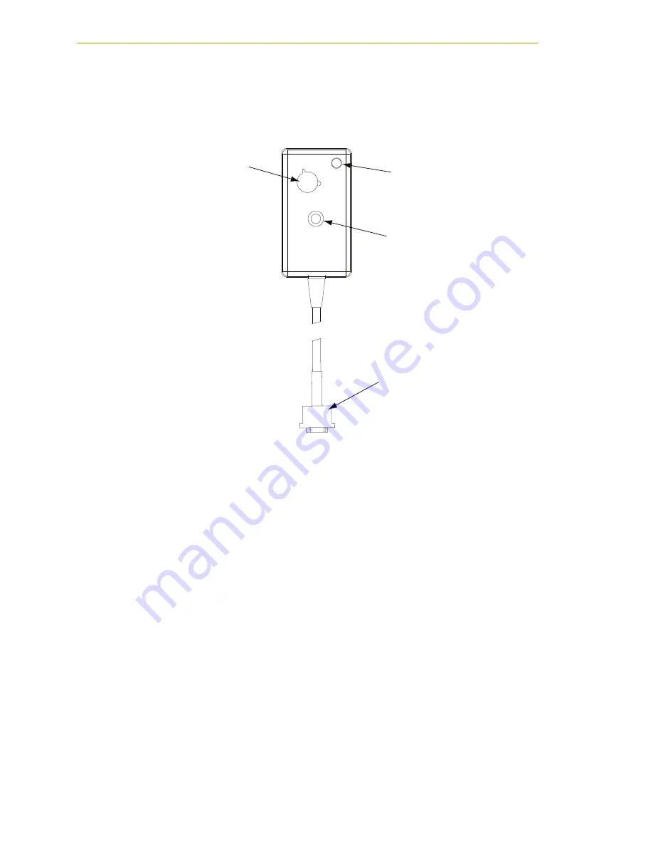
Figure 5-1. Manual Brake-Release Box
Using the Brake Release Switch on UL Robots
This procedure describes how to use the brake release switch on the base of UL robots. See
.
1. Make sure that high power is disabled (off).
2. Press one of the E-Stops (Pendant, Front Panel, or external).
NOTE:
An E-Stop must be activated in order for the brake release to work.
3. Using the axis selector switch, select the axis on which you want to release the
brake.
4. Depress the Brake Release push button, to release the brake.
5. Repeat
and
above to release the brakes on another axis.
NOTE:
When the Status LED (Green) is on, it indicates that the circuit is
enabled, when the Brake Release push button is pressed.
1
2 3 4
5
6
OFF
BRAKE
RELEASE
Axis selector switch
Status LED
Brake Release
Push button
9-pin male
D-Sub connector


