background image

Chapter 2 - Installation

26

Adept IO Blox User’s Guide, Rev B

Summary of Contents for IO Blox

Page 1: ...2006 3011 Triad Drive Livermore CA 94551 USA Phone 925 245 3400 Fax 925 960 0452 Otto Hahn Strasse 23 44227 Dortmund Germany Phone 49 231 75 89 40 Fax 49 231 75 89 450 41 rue du Saule Trapu 91882 Mass...

Page 2: ...ept MV4 Adept MV 5 Adept MV 8 Adept NanoBonder EBS Adept NanoBonder LWS Adept NanoCell Adept NanoStage L1P2 Adept NanoStage L3 Adept NanoStage L3P2 Adept OC Adept SmartAmp Adept SmartAxis Adept SmartC...

Page 3: ...ting 13 Cable Installation 14 2 4 Installation on an Adept Cobra s350 System 15 Mechanical Mounting 15 Cable Installation 15 2 5 Installation on an Adept Viper System 16 Mechanical Mounting 16 Cable I...

Page 4: ...ample Output Schematic 33 3 6 IO Blox LEDs 34 3 7 Custom Length IO Blox Cables 35 4 Operation on V Based Systems 37 4 1 Using the IO Blox with Adept Robots 37 Configuration 37 IO Signal Numbers 37 4 2...

Page 5: ...and AdeptOne with sEJI robots The IO Blox offers 8 inputs and 8 outputs all optically isolated You can connect up to four IO Blox devices per robot or MB 10 amp The IO Blox uses clamp style terminal s...

Page 6: ...on a specific topic Additionally the Document Menu provides a list of available product documentation To access the Adept Document Library type the following URL into your browser http www adept com M...

Page 7: ...Adept IO Blox User s Guide Rev B 7 Installation 2 2 1 Dimensions Figure 2 1 Adept IO Blox Dimensions 4 5 18 126 4 96 138 5 43 45 1 77 43 8 1 72 113 6 4 47 Tie Wrap Location 1 of 4...

Page 8: ...Section 2 5 on page 16 for information on connecting to an Adept Viper robot See Section 2 6 on page 17 for information on connecting to an AdeptOne with sEJI robot See Section 2 7 on page 18 for inf...

Page 9: ...e Name Length Part Number IO Blox to IO Blox 0 3 M 04679 003 IO Blox to IO Blox 1 1 M 04679 011 IO Blox to IO Blox 1 4 M 04679 014 IO Blox to IO Blox 1 8 M 04679 018 IO Blox to IO Blox 2 2 M 04679 022...

Page 10: ...hat was supplied with the system See Table 2 2 on page 9 for the details of the cable options 2 Plug one end of the cable into the JCBL2 connector on the first IO Blox 3 Plug the other end of the cabl...

Page 11: ...tems EXPIO connector on sEJI AdeptOne robot systems EXPIO connector on MB 40R Cobra s350 robot systems IO Blox connector on an MB 10 amp1 In custom or hybrid systems with multiple mechanisms the limit...

Page 12: ...bolt flanges from each end of the device 2 Remove one of the end caps by removing two Phillips head screws See Figure 2 3 3 Turn the device over and slide in the DIN rail foot element 4 Replace the e...

Page 13: ...oad this file The file contains the drawings showing mounting brackets for Cobra robots The table below shows the drawing numbers for the base and plate brackets required for mounting onto the robot s...

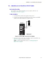
Page 14: ...ith the system 2 Connect the end of the cable with the matching D sub connector to the IO Blox connector on the robot See Figure 2 5 3 Connect the other end of the cable to the JCBL1 connector on the...

Page 15: ...ot cable supplied with the system 2 Connect the end of the cable with the matching D sub connector to the EXPIO connector on the MB 40R Figure 2 6 IO Blox Cable Connection to Cobra s350 Robot System 3...

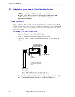
Page 16: ...e IO Blox to Robot cable supplied with the system 2 Connect the end of the cable with the matching D sub connector to the EXPIO connector on the sDAI module in the PA 4 power chassis Figure 2 7 IO Blo...

Page 17: ...A PHASE SHORT FAULT B PHASE SHORT FAULT C PHASE SHORT FAULT C O N T R O L S I G N A L A AMP M O T O R P O W E R O U T P U T DO NOT REMOVE OR INSTALLTHIS MODULE UNLESS HIGH VOLTS LED IS COMPLETELY EXT...

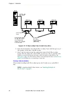
Page 18: ...to a three axis or four axis system IO Blox can be connected to the first and last MB 10 amps in the system Connecting the IO Blox to IO Blox Cable 1 Remove the T bracket cover from the MB 10 amp 2 Lo...

Page 19: ...the cable down to the desired length 1 Locate the IO Blox Auxiliary Power cable supplied with the IO Blox kit for Python Linear Modules 2 To connect to a single axis system or the first MB 10 amp in a...

Page 20: ...e 2 1 on page 7 for the location of the V and G terminals See Section 3 3 on page 28 for information on connecting to terminals Finishing Cable Installation When finished installing the IO Blox cables...

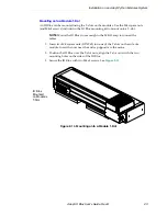
Page 21: ...M4x8 mounting screws included in the IO Blox mounting kit to mount the IO Blox IO Blox can also be mounted on a DIN rail see Mounting on a DIN Rail on page 12 Mounting onto an MB 10 Amp 1 Position the...

Page 22: ...sition the IO Blox on the L18 module end cap align the two mounting holes on the sides of the IO Blox with the corresponding two holes on the end cap 2 Secure the IO Blox to the T bracket cover with t...

Page 23: ...NOTE Mount the IO Blox close enough to the MB 10 amp to connect the cables 1 Insert two M4 square nuts DIN 562 into one of the T slots on the side of a module Insert the nuts near the end cap opposite...

Page 24: ...10 amp See Mounting onto an MB 10 Amp on page 21 for information 2 Optionally mount another IO Blox onto the T bracket cover on the other MB 10 amp See Figure 2 14 NOTE Below is a typical two axis Py...

Page 25: ...mount the IO Blox to the Z axis module position the IO Blox onto the enclosure on the Z axis module align the two mounting holes on the sides of the IO Blox with the corresponding two holes on the en...

Page 26: ...Chapter 2 Installation 26 Adept IO Blox User s Guide Rev B...

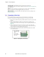
Page 27: ...an Adept Cobra i600 i800 robot refer to Chapter 5 for additional operation information for your robot For all other types of robots refer to Chapter 4 3 2 Connector and Switch Descriptions Figure 3 1...

Page 28: ...ocedure The terminals are designed for wire sizes in the range of 14 24 AWG 1 Strip 7 mm of insulation from the end of the wire that you want to connect to the terminal 2 Insert a small flat blade scr...

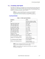
Page 29: ...ference Voltage sources are typically used to drive the inputs NOTE If using multiple power supplies ground all the power supplies to the same grounding point Table 3 1 IO Blox Input Specifications Pa...

Page 30: ...DIGITAL INPUTS 3 9K I2 UPR I2 LWR 3 9K I3 UPR I3 LWR PS2805 4 PS2805 4 A UPR B LWR 3 9K I4 UPR I4 LWR 3 9K I5 UPR I5 LWR PS2805 4 PS2805 4 A UPR B LWR 3 9K I6 UPR I6 LWR 3 9K I7 UPR I7 LWR PS2805 4 P...

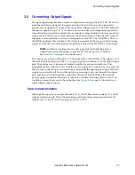
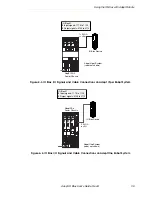
Page 31: ...hon Linear Modules to provide 24 VDC user power to IO Blox See Section 2 7 on page 18 for information The outputs are accessed through a 9 x 2 terminal block on the IO Blox The upper row of this termi...

Page 32: ...perational current range per channel See Total Current Limitation on page 31 Iout 700 mA Total Current Limitation all channels on Iin all on 2 5 A 50 C ambient Iin all on 3 7 A 25 C ambient On state r...

Page 33: ...8 VCC CLAMP CLAMP POWER CURRENT LIMITER JUNCTION TEMP DETCTION CASE TEMP DETCTION Same structure for all channels LOGIC I 1 DO_1 10K Typical Isolated Output Control 1 of 8 Typical User Supply and Loa...

Page 34: ...RTMP LED is active only when An output has been turned on by a V command and a One or more activated outputs has a thermal overload problem usually due to a short in the user s wiring from the output...

Page 35: ...O Blox Cable Parts List Item Adept Part Number Description Manufacturer Part Number 1 25146 50085 RCPT 8POSN MOLEX MICRO MOLEX INC 43025 0800 2 25119 02010 Terminal MOLEX MICRO 20 24 AWG MOLEX INC 430...

Page 36: ...Loc Wire Color Remarks P1 1 P2 1 WHT BLU GND Twist w LINE 5 P1 2 P2 2 BRN SIO1 Twist w LINE 3 P1 3 P2 3 WHT BRN SIO1 Twist w LINE 2 P1 4 P2 4 GRY TX232 Twist w LINE 8 P1 5 P2 5 BLU IO5VPWR Twist w LIN...

Page 37: ...hon Linear Modules Configuration IO Blox devices that are connected to the robot will be automatically recognized by the system when the robot is turned on You can connect or disconnect IO Blox device...

Page 38: ...Cable Connections on Adept Cobra s350 Robot System GND XSLV 1 2 SmartServo RS 232 XPANEL AC INPUT 200 240 VAC 1 24V DC INPUT 24 VDC XIO Cobra s600 s800 Robot IO Blox Device IO Blox 1 8 Input signals...

Page 39: ...T P U T Adept PA 4 Power Chassis IO Blox Device To EXPIO on sDAI IO Blox 1 8 Input signals 1113 to 1120 8 Output signals 0105 to 0112 Adept Viper System robot not shown adept technology inc PWM ON LOW...

Page 40: ...gure 4 5 IO Blox I O Signals and Signal Cable Connections on Python Module System Adept Python Module IO Blox Device To IO Blox Connector on MB 10 IO Blox 1 8 Input signals 1113 to 1120 8 Output signa...

Page 41: ...ee Section 4 4 on page 43 for information on using DC_SETUP The default signal configuration or mapping is shown in Table 4 2 This configuration is usually sufficient for most installations If you nee...

Page 42: ...r per robot or MB 10 amp to give you 32 inputs and 32 outputs per robot or amp For IO Blox devices installed on a a single robot or MB 10 amp by default IO Blox occupy the first four bytes of the thir...

Page 43: ...lox logical blocks 1 Type the following at the prompt load d util dc_setup v2 execute 1 a dc_setup The first screen in the Setup program looks similar to Figure 4 7 ROBOT 1 or MB 10 1 IO Blox 1 Output...

Page 44: ...n similar to Figure 4 8 is displayed Figure 4 8 DC_SETUP SmartServo Device Data Screen 4 Follow the on screen prompts to map IO Blox to the default logical block 5 If IO Blox are installed on a second...

Page 45: ...bove the default ranges used by other I O devices See Figure 4 12 on page 48 for the default signal input ranges for other I O devices See your robot documentation for additional information Map 8 ava...

Page 46: ...Blox User s Guide Rev B Figure 4 9 CONFIG_C Menu 2 Select option 2 V System Configuration Data The following will be displayed Figure 4 10 Controller Configuration Editor Menu 3 Select option 2 EDIT s...

Page 47: ...n Figure 4 12 on page 48 This figure shows an example from a CONFIG_C file look closely at the highlighted areas Do not delete any of the default configurations This file is configured for Two sDIO mo...

Page 48: ...T_BYTE 2 IO_OPTIONAL YES SIGNAL 1177 INPUT_BLOCK 4 INPUT_BYTE 3 IO_OPTIONAL YES SIGNAL 1185 INPUT_BLOCK 4 INPUT_BYTE 4 IO_OPTIONAL YES VIS_TRIGGER 1 SIGNAL NONE VIS_TRIGGER 2 SIGNAL NONE DIGITAL_OUTPU...

Page 49: ...robot is turned on You can connect or disconnect IO Blox devices while the system is turned on but you must issue a SRV RESET command to update the system IO configuration Figure 5 1 IO Blox I O Signa...

Page 50: ...gnal Designations Terminal Designation MicroV Signal Number IO Blox 1 Input 1 1033 Input 2 1034 Input 3 1035 Input 4 1036 Input 5 1037 Input 6 1038 Input 7 1039 Input 8 1040 Output 1 0033 Output 2 003...

Page 51: ......

Page 52: ...3011 Triad Drive Livermore CA 94551 925 245 3400 P N 04638 000 Rev B...

Reviews: