________________________________________________________Battery Charger
All specification are subject to change without notice
INSTRUCTION MANUAL 3
CBI123A_R8 Eng.doc
•
No jumper no Fast Charge (pos. 5)
Compensation Recharges in temperature (Only version XXX/ARJ)
Connecting to RJ45 (AUXILIARY OUTPUT) cable RJTEMP (supplied separately), the CBI is will vary the tension of battery charging in
function of the temperature:
•
Fast Charge:
-2.5mV/°C
•
Trickle Charge:
-1.5mV/°C
If the sensor is not connected or if the sensor is defective, the led Low Batt is on and the led Diagnosis continues to show the status of
the battery: trickle charge, fast charge or recovery charge.
N.B.:
the
sensor place on cable RJTEMP must be applied on the battery.
Cable connection
The following cable cross-sections may be used:
At the Input:
0.2÷2.5 mm
2
rigid / flexible
At the Output:
0.2÷2.5 mm
2
rigid / flexible
Strip the connection ends: 7mm
Input:
The input connection is made by the screw connections L, N, PE
.
Protection
On the primary side:
the device is equipped whit a internally fuse T 4 A/250Vac. If the internal fuse is activated, it is most probable
that there is a fault in the device. If happen, the device must be checked in the factory.
On the secondary side Battery and load:
The device is electrically protected against short circuits and overload.
Inversion polarity:
the module is protected against inversion of battery polarity.
Over current and output short circuit:
the unit limits the output current at max. 12 A in normal rating.
Deep discharge :
not possible. The unit disconnects the battery when a minimum voltage level is reached.
Battery Test:
Automatic. Every 20 sec. check polarity and battery. Every 4 hours in trickle charge, make the test of the battery
efficiency. The fault is signalized with relay commutation and diagnosis led blinking.
Characteristic Curves
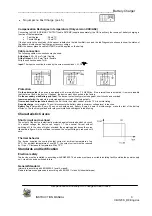
Short circuit and overload
The output of the device is electrically protected against overload and short circuit.
At nominal voltage the device can supply 1.1 the nominal Current without
switching off. In the case of higher overload, the operating point traces the curve
illustrated in figure. As the overload increases, the output voltage is reduced until
zero.
Thermal behavior
The device supplies the nominal output current at ambient temperature of up
50°C. For ambient temperature of over 50°C, the output current must be reduced
by 1% per °C increase in temperature. Max 70°C.
Standards and Certification
Electrical safety
The device must be installed in according with EN60950. The device must have a suitable isolating facility outside the power supply
unit, via which can be switched to idle.
General Standard
Immunity in according with EN50082-2, level 4, class B
Radio interference suppression in according with EN 55011 class A (industrial areas)


