background image

Mounting and connection 

MSX-Exxxx


www.addi-data.com 17 


1.4


Connecting peripherals  


Discharge any static by touching an earth wire. 


Remove the Ethernet system from its protective packaging. 

Information on cables and other accessories can be found in the accessories list of the MSX-E systems. 
 

1.4.1


Ethernet ports 


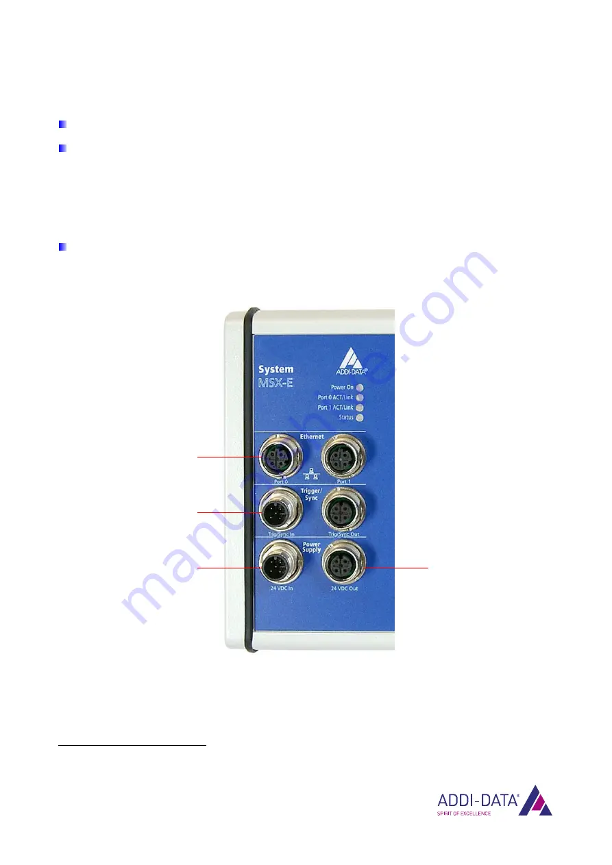
Plug the Ethernet cable into Ethernet Port 0

2

Fig. 1-10:  Connect peripherals 


2 If you want to connect several Ethernet systems, please read Chapter 1.5. 

Ethernet Port 0 

Trig/Sync In 

Current supply input  

(24 VDC In) 

Current supply output 

(24 VDC Out) 

Summary of Contents for MSX-E Series

Page 1: ...DIN EN ISO 9001 2008 certified Edition 02 05 07 2014 TECHNICAL DESCRIPTION MSX Exxxx Intelligent Ethernet system...

Page 2: ...use by third parties is not permitted unless this right has been granted by the product licence issued Non compliance with this could lead to civil and criminal proceedings ADDI DATA software product...

Page 3: ...or it Observe the instructions of this manual Make sure that you do not forget or skip any step We are not liable for damages resulting from the wrong use of the Ethernet system Pay attention to the f...

Page 4: ...ucture 24 2 2 1 Menu bar 24 2 2 2 ConfigTools Explorer 25 2 2 3 Actions 26 3 Function description General functions 28 3 1 Hardware trigger 28 3 2 Synchronisation and time stamp 29 3 2 1 Synchronisati...

Page 5: ...ing inwards 11 Fig 1 6 Angle bracket mounting 12 Fig 1 7 Mounting set Seal and screw short 12 Fig 1 8 Mounting set Original screw seal and screw long 12 Fig 1 9 Connectors 13 Fig 1 10 Connect peripher...

Page 6: ...22 Data server Blocking TCP IP transfer 46 Fig 4 23 Data server Data caching 46 Fig 4 24 Ring buffer 48 Fig 4 25 Data server What do you want to do 49 Fig 5 1 Overview Servers 50 Fig 5 2 SOAP in the...

Page 7: ...for example to adapt the IP address of the MSX E system when using the system for the first time 3 Description of general functions e g Customer Key 4 Description of the web interface of the MSX E sy...

Page 8: ...se follow the safety precautions An improper handling of the Ethernet system may cause property damage and injury Discharge any static by touching an earth wire Remove the Ethernet system from its pro...

Page 9: ...ype label contains for example the product name including the specific version name and the serial number of the Ethernet system In case of queries these details always have to be kept at hand For mor...

Page 10: ...s adequately secured for transport The Ethernet system could for example fall off the DIN rail which could cause damage to the Ethernet system and or other objects or injury of persons Mount the Ether...

Page 11: ...roceed as follows NOTICE The housing of the Ethernet system must not be opened or the warranty claim will be invalid see also the system specific MSX E manual Chapter 1 2 4 For this reason the housing...

Page 12: ...der of the mounting process please use only the short seals and screws from the mounting set Fig 1 7 Mounting set Seal and screw short The original screw from the MSX E system and the long seals or sc...

Page 13: ...th the other screw holes Once you have mounted the brackets on the Ethernet system you can attach the system directly to other devices or machines by using other screws 1 3 Pin assignment In this chap...

Page 14: ...splay Port 0 ACT Link or Port 1 ACT Link gives you information on the status of the corresponding interface For more details see Chapter 1 6 1 NOTICE The LED display only works if the MSX E system is...

Page 15: ...ger synchro cable Table 1 3 Trigger synchro cables Name Cable end Length CMX 40 Open end female connector 5 pin 1 5 m CMX 41 Open end female connector 5 pin 3 m CMX 42 Open end female connector 5 pin...

Page 16: ...ssignment Voltage supply Power Supply In Power Supply Out Cable black Pin No Connector 5 pin M12 Female connector 5 pin M12 Lead colour 1 24 V 24 V brown 2 24 V 24 V white 3 Ground Ground blue 4 Groun...

Page 17: ...packaging Information on cables and other accessories can be found in the accessories list of the MSX E systems 1 4 1 Ethernet ports Plug the Ethernet cable into Ethernet Port 02 Fig 1 10 Connect per...

Page 18: ...cable into the input 24 VDC In 1 see Fig 1 10 1 4 4 Sensors or actuators Information concerning the type of sensor or actuator the corresponding pin assignment as well as connection examples can be fo...

Page 19: ...ibility to connect several Ethernet systems to the MSX Exxxx In order to do so proceed as follows Connect the first Ethernet system see description at the beginning of this chapter Connect the compone...

Page 20: ...energy saving mode No display There is no voltage applied Power On Lights green Voltage is applied The system is ready for operation No display There is no network connection Lights yellow Port 0 ACT...

Reviews: