background image



























SECT 4

Operation

In operation, the Adder unit allows you to quickly switch between up to four 
systems. One system can be accessed at a time, whereupon the common 
keyboard, mouse, video monitors and serial channels are linked to that system. 
The Adder unit deceives the other systems that they still have their peripherals 
connected to them in order that they respond quickly and correctly once they 
are again selected.

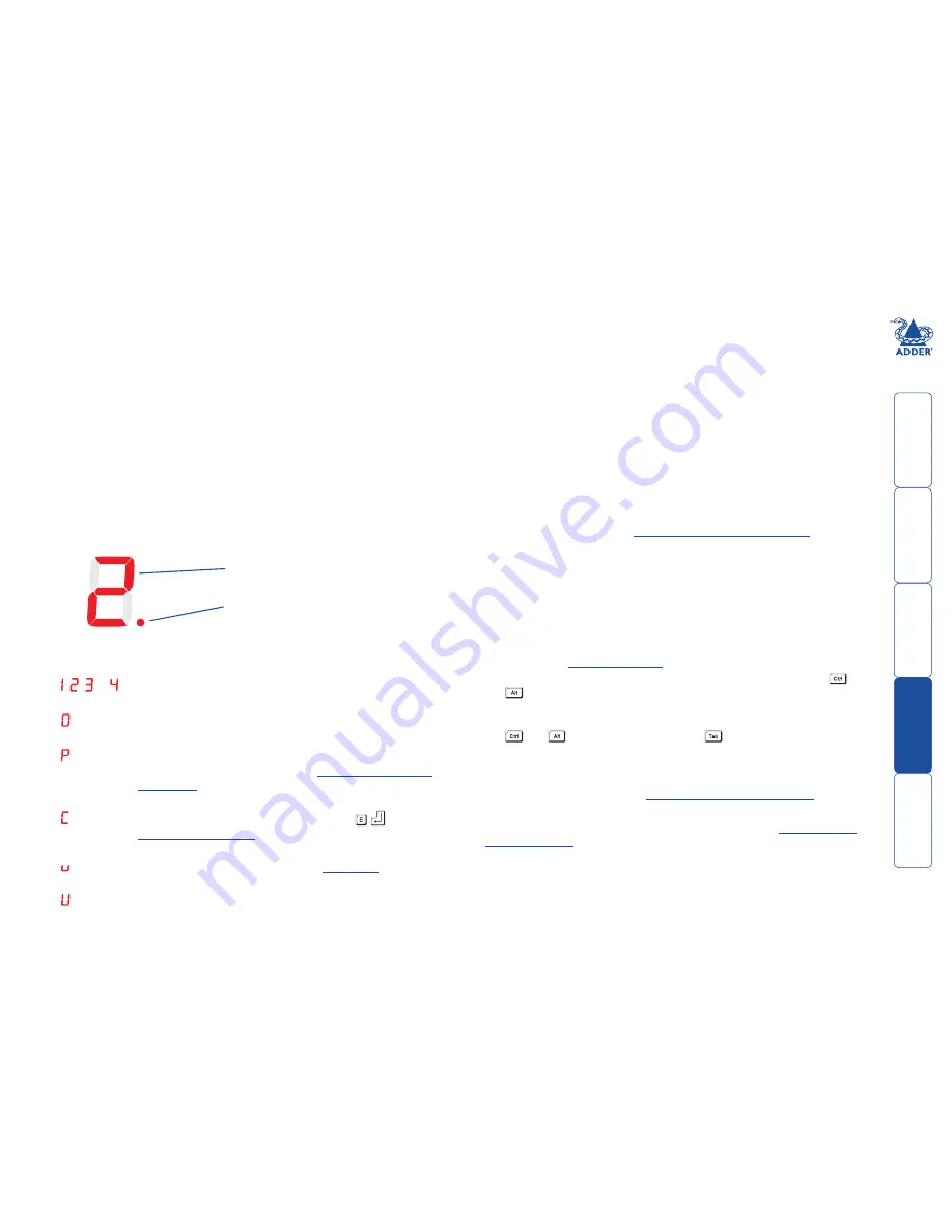
The 

SYSTEM

 readout

On the front panel of the Adder unit, the 

SYSTEM

 readout indicates either: 

•  The computer system to which the keyboard and mouse are connected, or
•  An alternative mode of operation, such as password protected mode, 

configuration mode, upgrade mode, etc.

Typical 

SYSTEM

 readout displays are:

,  ,   or   

Indicates the currently selected system. The selected channel 
will also be indicated on the remote control.


The Adder unit is disabled, no system is currently selected. The 
remote control will not show any channel indication.


The Adder unit is password protected. You must enter the 
current password to gain access. See 

Setting.(or.changing).

a.password

 for details. The remote control will not show any 

channel indication.


Configuration mode is currently active. Press   

 to exit. See 

Configuration.options

 for details. The remote control will not 

show any channel indication.


Upgrade mode is currently active. See 

Upgrading

 for details. 

The remote control will not show any channel indication.


The upgrade process is complete. Set mini switch 7 to OFF to 
exit upgrade mode. 

Main digit indicates currently selected system 
or other modes - see below for details.

Flashing dot indicates keyboard 
and/or mouse activity.

Selecting systems

There are four ways to select a system:

•  The Adder unit front panel button
•  The optional Remote control selector
•  Keyboard hotkey combinations
•  Mouse button combinations

To use the Adder unit front panel button

Note: You can determine whether the Adder unit visits every port in turn 
(regardless of whether active systems are connected to them) or only those with 
active systems connected. See 

All channel/active channel cycling

 for details.

•  Press the 

SELECT

 button repeatedly until the 

SYSTEM

 readout shows the 

required system number.

To use the remote control selector

•  Press the remote control button that corresponds to the required system. The 

adjacent indicator will illuminate to show that the chosen system is selected. 

To use keyboard hotkey combinations

Note: The standard hotkeys can be changed to avoid clashes with software 
applications, see 

Changing hotkeys

 for details.

• 

To.select.a.particular.system:

 Press and hold the hotkeys (usually 

 and 

), then also press the number of the required system and release all three 

keys.

• 

To.select.the.next/previous.system:

 Press and hold the hotkeys (usually 

 and 

), then press and release the 

 key until the required system is 

selected. Release the hotkeys.


Note: You can determine whether the Adder unit visits every port in turn 
(regardless of whether active systems are connected to them) or only those with 
active systems connected. See 

All channel/active channel cycling

 for details.

To use mouse button combinations

Note: The mouse button arrangements can be changed, see 

Mouse button 

switching modes

 for details.

•  Press and hold the mouse scroll wheel (or centre mouse button) and then 

press either the left mouse button to change to the next system or the right 
mouse button to change to the previous system. 

Summary of Contents for SmartView MultiScreen

Page 1: ...SmartView Multiscreen Serial Four port KVM and serial switch SMARTVIEW MULTISCREEN ...

Page 2: ...artView Multiscreen Serial units 11 Hot plugging and mouse restoration 12 Operation The SYSTEM readout 13 Selecting systems 13 Configuration options 14 Setting or changing a password 14 Changing hotkeys 14 Mouse button switching modes 15 All channel active channel cycling 15 Automatic screen saver 15 Autoscanning computer selection 16 Autoscanning dwell timing 16 Miscellaneous functions 16 Resetti...

Page 3: ...and serial device per switched port SVMS4 DS supports dual video monitors and serial devices per switched port Serial line switching In common with all other Adder switches the SmartView Multiscreen Serial provides completely transparent switching for the serial lines in unison with the keyboard video and mouse channels Apart from the ground connections of each serial port which remain permanently...

Page 4: ...dard items Adder SmartView Multiscreen Serial model SVMS4 S A 4A 3A 2A 1A B 4B 3B 2B 1B C 4C 3C 2C 1C D 4D 3D 2D 1D OPTIONS FLASH OPTIONAL POWER INDOOR USE ONLY 5V 1A Adder SmartView Multiscreen Serial model SVMS4 DS One video input and one serial channel per port Two video inputs and two serial channels per port ...

Page 5: ... metres two required per system Adder P N VSC3 Additional and optional items CCP2U converter required when connecting to a system that uses a USB keyboard and mouse two VSC3 cables are also required Adder P N CCP2U RC4 remote control plus link cable Flash upgrade link cable Converter for connecting a SUN computer to the Adder unit not pictured Adder P N CCSUN RC1 remote control plus link cable ...

Page 6: ...g that its connection cables are no longer than 2 metres Thanks to the remote control the Adder unit can be situated out of sight behind a desk or adjacent to the systems Consult the precautions listed within the Safety information section Mounting Before you begin connecting to the keyboard mouse and source systems it is advisable to mount the unit in place either On a horizontal surface using th...

Page 7: ... end of the VSC3 link cable to the inline keyboard socket of the CCP2U converter 3 Repeat steps 1 and 2 for the mouse connection green between the Adder unit port and the CCP2U converter 3 Attach the other end of the VSC3 link cable to the keyboard socket usually coloured purple on the first system 4 Repeat steps 1 and 2 for the mouse connection green between the Adder unit port 1 and the first sy...

Page 8: ...els only 5 Repeat all of the above steps for each port to be used To make serial links 1 Ensure that the computer systems to be connected are switched off and that no power is applied to the Adder unit Note If it is not possible to switch off systems prior to connection then a Hot plug procedure is available see the Hot plugging and mouse restoration section for more details 2 At the rear panel of...

Page 9: ...portant Please read and adhere to the electrical safety information given within the Safety information section of this guide In particular do not use an unearthed power socket or extension cable To connect the optional power supply 1 Attach the output connector of the power supply country specific power supplies are available to the socket on the far left of the rear panel of the Adder unit 2 Whe...

Page 10: ...o do this the serial device must be connected to the OPTIONS FLASH port on the rear panel of the unit using an appropriate link cable 1A 1B 1C OPTIONS FLASH The serial device must use the following speed protocol settings 1200 baud 8 bits no parity and 1 stop bit No handshaking is used by the SmartView Multiscreen Serial To perform the switching operation simply send the character for the required...

Page 11: ...ch unit Cascade system selection The quickest way to access cascaded systems is to use hotkey sequences 1 Simultaneously press and hold and Note The and keys when pressed in combination are called hotkeys and they signal to the Adder unit that you wish to control it rather than the computer However if these particular hotkeys clash with another device or program then you can change them to a diffe...

Page 12: ...he OPTIONS FLASH ports of the two Adder units see page 18 for pinout details Whenever the master Adder unit s channel is switched it sends a command to the slave unit to make it do the same The slave unit requires the optional power adapter because it does not have keyboard connections to either of the systems The SmartView Multiscreen Serial may also be synchronised together with AdderView GEM pr...

Page 13: ...ort among other features the scroll wheel function If the mouse has a scroll wheel then it is likely to support the IntelliMouse format If it is a Microsoft branded mouse then it will usually state that it is an IntelliMouse on its underside label Recognising an IntelliMouse driver Before hot plugging to the Adder unit or afterwards using only keyboard control access the Windows Control Panel of t...

Page 14: ...eyboard and or mouse activity Selecting systems There are four ways to select a system The Adder unit front panel button The optional Remote control selector Keyboard hotkey combinations Mouse button combinations To use the Adder unit front panel button Note You can determine whether the Adder unit visits every port in turn regardless of whether active systems are connected to them or only those w...

Page 15: ...re not differentiated 2 Press The SYSTEM readout should show the number of the first available system If the password is forgotten 1 Remove power from the Adder unit If any systems are active either switch them off or remove their keyboard link connectors from the Adder unit If an optional power supply is used remove it 2 Press and hold the SELECT button and re apply at least one source of power T...

Page 16: ...ption when cycling between the system channels to visit each channel irrespective of whether an active system is connected or to only select active channels You can affect the keyboard mouse setting independently from the front panel SELECT switch setting To change keyboard mouse channel cycling 1 Enter configuration mode Press and hold the SELECT button until the SYSTEM readout shows c 2 Press fo...

Page 17: ...t each computer for 60 seconds before switching to the next port Miscellaneous functions These configuration options contain a mixture of functions from discovering the Adder unit internal software firmware revision to restoring mouse function to resetting all configuration changes Note These functions use the letter F As with all of the other configuration options press the letter and then the nu...

Page 18: ... unit If an optional power supply is used remove it 3 Connect the upgrade cable between the remote control socket on the right side of the Adder unit rear panel and a vacant serial port on the system containing the upgrade files 4 On the underside of the unit click mini switch 7 to its ON position 5 Re apply power to the Adder unit and switch on the system to be used for the upgrade The SYSTEM rea...

Page 19: ... cheaper mice are not fully compatible with the Adder unit and can lose data causing the channel to be changed if mouse switching of channels is enabled Ensure that you are using a Microsoft compatible mouse driver on your system Some other manufacturers drivers may switch the mouse to use a proprietary mouse data format not supported by the Adder unit If you have unplugged and re connected a mous...

Page 20: ...it or its remote control yourself The optional power adapter can get warm in operation do not situate it in an enclosed space without any ventilation The Adder unit does not provide ground isolation and should not be used for any applications that require ground isolation or galvanic isolation When using the optional power adapter use only with a grounded outlet When using a backup power supply UP...

Page 21: ... is connected d Consult the supplier or an experienced radio TV technician for help FCC Compliance Statement United States This equipment generates uses and can radiate radio frequency energy and if not installed and used properly that is in strict accordance with the manufacturer s instructions may cause interference to radio communication It has been tested and found to comply with the limits fo...

Page 22: ...o ADD0069 Adder Technology Limited Technology House Trafalgar Way Bar Hill Cambridge CB3 8SQ United Kingdom Tel 44 0 1954 780044 Fax 44 0 1954 780081 Adder Corporation 29 Water Street Newburyport MA 01950 United States of America Tel 1 888 932 3337 Fax 1 888 275 1117 www ctxd com Documentation by ...

Reviews: