12
Making connections
Connections to the AdderView Secure unit do not need to follow the precise
order given in this user guide, although if one or more systems must be hot-
plugged, connect these after all other connections have been made.
IMPORTANT: To achieve the high levels of signal isolation and low emissions
profile that the switch is capable of delivering, it is necessary to use the only the
cables listed in the
Additional items
section. These have been very carefully
designed and tested to maximize the performance levels of the switch.
Note: For additional security, use tamper-evident tape to bridge the computer
cable connections to the switch’s case once installed.
Connections to computer systems
All connections to computer systems are achieved using combined shielded link
cables of which there are several different types to suit the various ports used -
see the
Additional items
section for details.
See also
Devices used with the AdderView Secure
for advice about linking
devices to the AdderView Secure unit.
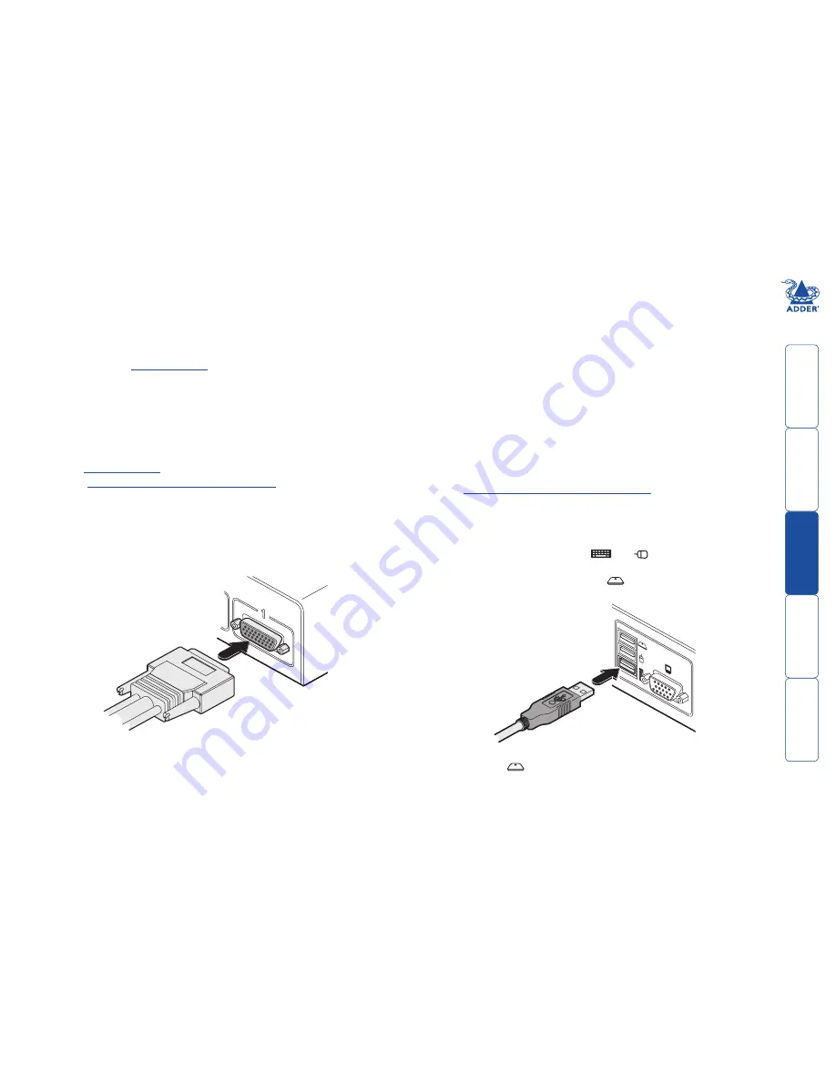
To connect a system link
1 Wherever possible, ensure that power is disconnected from the unit and the
host computer(s) to be connected.
2 At the rear panel of the unit, connect the appropriate link cable to the 26-
way connector of the appropriate channel.
Connections to user console peripherals
To connect a keyboard and mouse
IMPORTANT: To reduce the risk of radiated snooping, do not use wireless
keyboard or mouse devices.
See also
Devices used with the AdderView Secure
for advice about linking
devices to the AdderView Secure unit.
1 Wherever possible, ensure that power is disconnected from the unit and the
host computer(s) to be connected.
2 In the middle of the rear panel, connect the cables from the keyboard and
mouse to the USB sockets marked
and
respectively.
Note: If using a combined keyboard and smartcard reader then connect the
keyboard/reader to the socket labeled
. Any keyboard connected to the
keyboard socket should then be removed as it will become non-functional).
3 Attach the connectors at the other end of the link cable to the appropriate
ports of the computer, i.e. VGA video, USB (or PS/2 keyboard and mouse)
and the smart card reader, if used - see below.
IMPORTANT: If only certain computers require the use of the smart card
reader, for those systems use a link cable that has only one USB connector -
do not leave a spare USB link unconnected.
CO
NS
OL
E
3 If using a smart card reader, connect the cable from the reader to the USB
socket labeled
.
Note: The smartcard port is not active on standard models (AVSV1002-XX
and AVSV1004-XX) which do not contain smartcard circuitry.


