background image

12

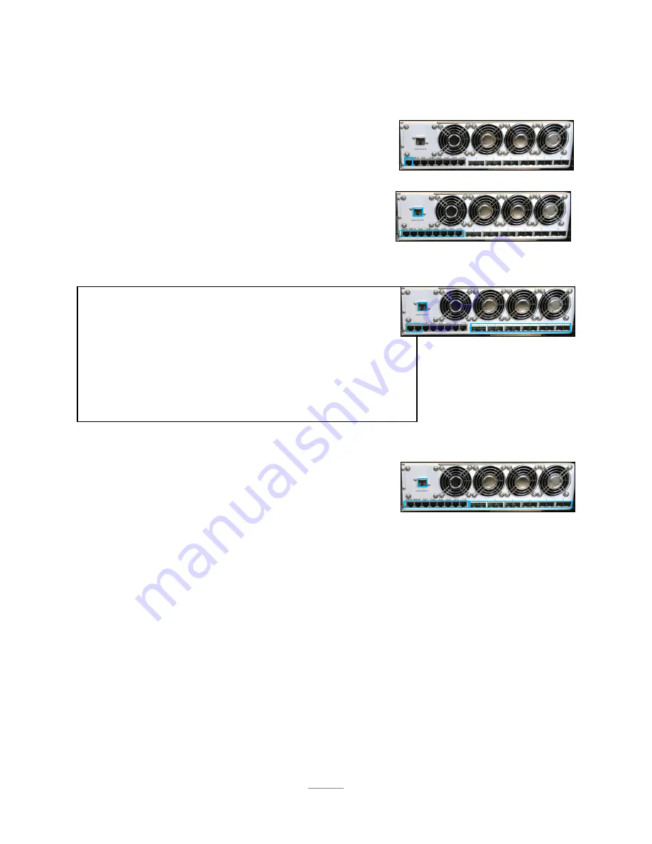
Section 2.5 - Networking Your SR-60

Section 2.5.1 - Minimal/Testing Equipment

Section 2.5.2 - 1Gbps Networking Schema

Section 2.5.3 - 10Gbps Networking 

(with ROMWare Switch Management)

Section 2.5.4 - 10Gbps Networking 

(without Out of Band Switch Management)

1 10/100 Ethernet Cable

1 External Computer (eg. a laptop)

3 10/100 Ethernet Cables

6 10/100/1000 Ethernet Cables

1 10 port (or more) 10/100/1000 Ethernet Switch

3 10/100 Ethernet Cables

1 4 port (or more) 10/100 Ethernet Switch

Six or twelve SFP+ 10Gbps Cables (included)

If using 6 10Gbps SFP+ Cables:


1 8-port (or more)SFP+ 10Gbps Ethernet Switch

or, if using 12 SFP+ 10GbpsCables:


1 16-port (or more) SFP+ 10Gbps Ethernet Switch

All equipment found in Section 2.5.2, plus the following:

Six or twelve SFP+ 10Gbps Cables (included)

If using 6 SFP+ 10Gbps Cables:


1 8-port (or more) SFP+ 10Gbps Ethernet Switch

or, if using 12 SFP+ 10GbpsCables:


1 16-port (or more) SFP+ 10Gbps Ethernet Switch

RECOMMENDED

Summary of Contents for BioDigitalPC SR-60

Page 1: ...SR 60 USER GUIDE PLUG INTO THE FUTURE OF TECHNOLOGY...

Page 2: ...2 Revision History Revision Notes V2 5 Revision 2 5 was published in November of 2017...

Page 3: ...2 6 Powering On Your SR 60 13 Section 3 SR 60 Overview 14 Section 3 1 SR 10 Modules 15 Section 3 2 Rear Panel 16 Section 3 3 Front Panel 17 Section 4 ROMWare Software 18 Section 4 1 Login 18 Section 4...

Page 4: ...the SR 60 server solution Installations will be supported by ADDC Unless otherwise specified all instructions provided in this manual will assume that a user is a trained technician How to Read this...

Page 5: ...Top Cover Comes Assembled BioDigitalPC Server Cards Check Invoice for Quantity 4 AC DC Power Supplies 12 10Gbps SFP Cables 4 AC Power Cords 2 Rack Slides Section 1 1 What s in the Box 10Gbps SFP Cabl...

Page 6: ...learance of 20in 50 8cm behind the rack Temperature Considerations Your SR 60 is designed to operate at room temperature with its self contained cooling Power Considerations When properly configured a...

Page 7: ...or the rack must be bolted to the floor before you slide the unit out for servicing Failure to stabilize the rack can cause the rack to tip over and cause severe injury to the technicians and damage...

Page 8: ...Align the inner rails into the extended outer rails and push the chassis to the rear of the rack Optional Screw the handles to the rack Top Cover not shown Section 2 2 Installing Your SR 60 into a Ra...

Page 9: ...the SR 60 System Cover and access any of the components inside the system Section 2 3 2 Installing a BioDigitalPC Step 3 Insert Card with Arnouse Digital Devices Corp facing upwards and the connector...

Page 10: ...Section 2 3 3 Removing a BioDigitalPC Section 2 3 Installing Your BioDigitalPC s e al Once complete a technician should replace the SR 60 Top Cover Step 3 Reset the ejection bar to the original posit...

Page 11: ...t SR 60 Power Supply 4 You should see the OK LED illuminated green Handle Tab Correct orientation pictured inserting power supplies upside down may damage the system The SR 60 requires two power suppl...

Page 12: ...10 port or more 10 100 1000 Ethernet Switch 3 10 100 Ethernet Cables 1 4 port or more 10 100 Ethernet Switch Six or twelve SFP 10Gbps Cables included If using 6 10Gbps SFP Cables 1 8 port or more SFP...

Page 13: ...Configuration Section 2 6 1 Single Feed Redundant Power Supply Configuration Power Source A Power Source A Power Source A Power Source A Power Source A Power Source A Power Source B Power Source B Eac...

Page 14: ...14 Section 3 SR 60 Overview Network Connections Module Module Number Corresponding LED Label Card Slot Number LEDs...

Page 15: ...grated switch Each switch has two SFP 10Gbps connectors and one 1Gbps RJ 45 connector broken out to the rear panel of the SR 60 See Section 3 2 for additional information Each SR 10 s integrated switc...

Page 16: ...ent Hardware Ports 1Gbps Ports Section 3 2 Rear Panel Management Ports AC Power 10Gbps SFP Ports Section 3 2 2 Management Ports Section 3 2 1 AC Power Section 3 2 3 10Gbps SFP Ports 1 2 3 4 KVM Over I...

Page 17: ...SFP Port Shown as Port 32 in the SR 10 Switch Web GUI 10G B An SR 10 s secondary 10Gbps SFP Port Shown as Port 33 in the SR 10 Switch Web GUI 10G AUX An SR 10 s auxiliary one Gigabit Shown as Port 31...

Page 18: ...or monitoring of your SR 60 Users are supplied with administrative credentials that have been factory set Only one admin can be logged in at once Section 4 1 Login 10 11 12 13 14 15 16 17 18 19 20 21...

Page 19: ...19 Section 4 3 AC Power Monitoring Information about the AC DC Power Supplies can be shown by clicking the Power AC to DC GUI Element...

Page 20: ...sers to turn On and Off each SR 10 Power Module Clear Faults will clear faults for this SR 10 s power supply To verify the SR 10 s Power Supply is operating optimally you can press the button labeled...

Page 21: ...via another Web GUI Web GUI Graphical Interface for configuring the selected switch Section 4 5 SR 10 Switch Configuration Displaying the switch management for selected SR 10 is done by clicking Swit...

Page 22: ...a signal to the BioDigitalPC Server card to shut down gracefully Removes power from the BioDigitalPC Server card waits 30 seconds and then applies power back to the BioDigitalPC Server card Removes po...

Page 23: ...of the SR 10 Module within the SR 60 BioDigitalPC Slot Position The Position of the Slot within the SR 10 Current Status Displays the current status of the slot Present Not Present On and Off Hardware...

Page 24: ...r boot up of the SR 60 the BioDigitalPC in this slot will be powered on if present after Delay number of seconds Delay The number of seconds to wait after power up of the SR 60 before powering on the...

Page 25: ...Switch Serial Interface Select the SR 10 Module Number for the switch you would like to manage Enter your serial command here Click to send the specified command to the switch Clear all command histor...

Page 26: ...system components Results will be displayed on screen when completed Appendix A Run an SR 60 Component Test Displaying the system components test for the SR 60 is done by clicking the gear symbol then...

Page 27: ...27 If any field is shown as RED instead of as GREEN please contact ADDC Support for further diagnostics and troubleshooting Appendix B A Successful SR 60 Component Test...

Page 28: ...WWW ADDC NET 516 673 4444 INFO ADDC NET...

Reviews: