ADC AD-190 Installation Manual Download Page 29

113354-23

www.adclaundry.com

25

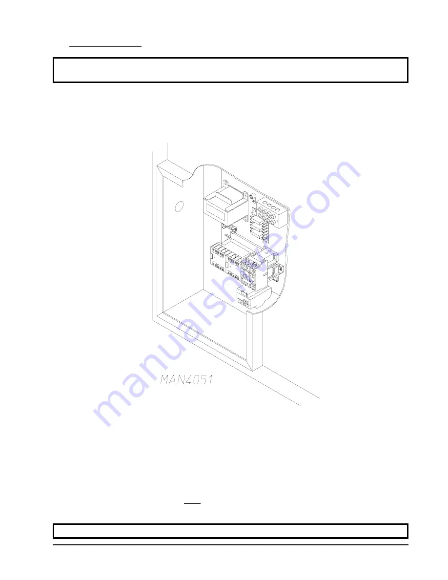
3. Electrical Connections

NOTE: A wire diagram is included with each dryer and is affixed to the back side of the top control

(access) door.

The only electrical input connections to the dryer are the 3-phase (3ø) power leads (L1, L2, and L3),
GROUND, and in the case of 4 wire service, the NEUTRAL.  These electrical connections are made at
the terminal block located in the service/relay box at the rear, upper left hand corner of the dryer.  To gain
access into this service box, the service cover must be removed.

The “LINE POWER” and the “GROUND” connections to the dryer must be made through the knockout
hole at the top of the electric service/relay box.  A strain relief must be used where the line power ground
wires go into the electric service/relay box.

Providing local codes permit, power connections to the dryer can be made by use of a flexible underwriters
laboratory list cord/pigtail (wire must conform to ratings of the dryer), or the dryer can be hard wired
directly to the service breaker.  In ALL cases, a strain relief must be used where the wire(s) enter the
dryer’s electrical service (relay) box.

NOTE: A CIRCUIT SERVICING EACH DRYER MUST BE PROVIDED.

Summary of Contents for AD-190

Page 1: ...la zone Appelez imm diatement votre fournisseur de gaz depuis un voisin Suivez les instructions du fournisseur Si vous ne pouvez rejoindre le fournisseur de gaz appelez le service des incendies L inst...

Page 2: ...ely and promptly These instructions are only valid if the following country code is on the appliance If this code is not present on the appliance it is necessary to refer to the technical instructions...

Page 3: ...when servicing controls Wiring errors can cause improper operation Attention Au moment de l entretien des commandes tiquetez tous les fils avant de les d brancher Des erreurs de c blage peuvent entra...

Page 4: ...the ambient temperature remains between 40 F 4 44 C and 130 F 54 44 C WARNING UNDER NO CIRCUMSTANCES should the dryer door switches the lint drawer switch or the heat safety circuit ever be disabled...

Page 5: ...Steam Information 31 I Preparation for Operation Start Up 35 J Preoperational Test 36 K Preoperational Instructions 38 L Compressed Air Requirements 39 M Shutdown Instructions 40 SECTION IV SERVICE P...

Page 6: ...appliance b DO NOT touch any electrical switch c DO NOT use any phone in your building d Clear the room building or area of ALL occupants e Immediately call your gas supplier from a neighbor s phone...

Page 7: ...UNDER NO CIRCUMSTANCES should the dryer door switches the lint drawer switch or the heat safety circuit ever be disabled WARNING PERSONALINJURYOR FIRE COULD RESULT SHOULD THE DRYER DOOR SWITCHES THE L...

Page 8: ...________________________________________________________________ ___________________________________________________________________________________________________________________________ ___________...

Page 9: ...N A APPROX NET WEIGHT APPROX SHIPPING WEIGHT AIRFLOW EXHAUST CONNECTION DIAMETER COMPRESSED AIR CONNECTION COMPRESSED AIR VOLUME OVEN SIZE kW Btu hr kcal hr VOLTAGE AVAILABLE 208 575v 3 3 4w 50 60 Hz...

Page 10: ...6 American Dryer Corp 113354 23 NOTE ADC reserves the right to make changes in specifications at any time without notice or obligation 190 SPECIFICATIONS...

Page 11: ...113354 23 www adclaundry com 7 190 SPECIFICATIONS Steam with Optional Steel Steam Coil NOTE ADC reserves the right to make changes in specifications at any time without notice or obligation...

Page 12: ...6 18 kg TUMBLER DIAMETER 55 5 8 141 29 cm TUMBLER DEPTH 43 1 2 110 49 cm TUMBLER VOLUME 61 20 cu ft 1732 99 L TUMBLER DRIVE MOTOR 3 hp 2 24 kW BLOWER FAN MOTOR 7 1 2 hp 5 59 kW DOOR OPENING DIAMETER 3...

Page 13: ...113354 23 www adclaundry com 9 190DR SPECIFICATIONS NOTE ADC reserves the right to make changes in specifications at any time without notice or obligation...

Page 14: ...View Illus No Description 1 Microprocessor Control Keypad Panel Assembly controls 2 Control top access Door Assembly 3 Main Door Assembly 4 Lint Drawer 5 Lint Door 6 Wire Diagram located behind contr...

Page 15: ...113354 23 www adclaundry com 11 2 Dryer Front Internal View Illus No Description 1 Drive tumbler Motor 2 Drive Assembly 3 Blower Motor 4 IdlerAssembly 5 Installation Label 6 Data Label 7 Heating Unit...

Page 16: ...d from the floor area that the dryer is to rest on IMPORTANT Thedryermustbeinstalledonnoncombustiblefloorsonly 2 The dryer must not be installed or stored in an area where it will be exposed to water...

Page 17: ...location while still attached to the skid or with the skid removed To unskid the dryer locate and remove the four 4 lag bolts securing the base of the dryer to the wooden skid Two 2 are at the rear b...

Page 18: ...ryer b Remove the eight 8 sets of nuts and washers B in the illustration below holding the console module to the base c Disconnect the white plug connector C in the illustration below located on the t...

Page 19: ...nce of 12 inches 30 48 cm is required providing no sprinkler is located above the dryer For steam dryers or if a sprinkler is located above the dryer 18 inches 45 72 cm is required D Dryer should be p...

Page 20: ...onsideration to ensure proper performance of each dryer An unrestricted source of air is necessary for each dryer As a general rule an unrestricted air entrance from the outdoors atmosphere of a minim...

Page 21: ...s possible Single or independent dryer venting is recommended NOTE Make up air openings should not be located in an area directly near where the exhaust vents exitthebuilding The shape of the ductwork...

Page 22: ...Fuel Gas Code Exhaust ducts forType 2 clothes dryers shall be constructedofsheetmetalorothernoncombustiblematerial Suchductsshallbeequivalentin strength and corrosion resistance to ducts made of galva...

Page 23: ...or periodic inspection and cleaning of lint from the ductwork Vertical Venting When single dryer vertical venting is used the length of ductwork from the dryer to the outside exhaust outlet must not e...

Page 24: ...mmon Venting If it is not feasible to provide separate exhaust ducts for each dryer ducts from individual dryers may be channeled into a common main duct The individual ducts should enter the bottom o...

Page 25: ...roportion if the main duct run to the last dryer to where it exhausts to the outdoors is unusually long over 20 feet 6 1 meters or has numerous elbows more than one 1 in it In calculating ductwork siz...

Page 26: ...in the exhaust duct between zero and 0 3 inch water column Where employed booster fans must not activate the dryer airflow proving switch sail switch when the dryer is notin operation The ductwork sho...

Page 27: ...ualcanresultinpersonalinjuryorcomponentfailure NOTE ComponentfailureduetoimproperinstallationwillVOIDTHEWARRANTY Each dryer should be connected to an independently protected branch circuit The dryer m...

Page 28: ...vice specifications of the data label exactly WARNING 208 VACAND 240 VACARE NOT THE SAME Any damage done to dryer componentsduetoimpropervoltageconnectionswillautomatically VOIDTHE WARRANTY NOTE ADC r...

Page 29: ...ervice box the service cover must be removed The LINE POWER and the GROUND connections to the dryer must be made through the knockout hole at the top of the electric service relay box A strain relief...

Page 30: ...left hand corner of the dryer For added personal safety when possible it is suggested that a separate ground wire sized per local codes be connected from the ground connection of the dryer to a groun...

Page 31: ...OIDTHEWARRANTY WARNING FIRE OR EXPLOSION COULD RESULT DUE TO FAILURE OF ISOLATINGOR DISCONNECTINGTHE GAS SUPPLYAS NOTED 1 Gas Supply The gas dryer installation must meet the American National Standard...

Page 32: ...a refer to data plate Shaded areas are stated in metric equivalents Measured at the gas valve pressure tap when the gas valve is on b Gas Connections Inlet connection 1 1 2 N P T Inlet supply size 1 1...

Page 33: ...line etc Specific information regarding supply line size should be determined by the gas supplier NOTE Undersizedgassupplypipingcancreatealoworinconsistentpressure whichwillresultin erraticoperationo...

Page 34: ...orp 113354 23 NOTE Thedryermustbeisolatedfromthegassupplypipingsystembyclosingitsindividualmanual shutoff valve during any pressure test of the gas supply system at test pressures equal to or less tha...

Page 35: ...ntained between a value of 9 5 to 10 5 These limits are set to limit the acid attack of the steam coils IMPORTANT CoilfailureduetoimproperpHlevelwillVOIDTHEWARRANTY 2 Steam Requirements High Pressure...

Page 36: ...to the coil as possible 1 An inverted bucket steam trap with a capacity of 1 080 lb 491 kg of condensate per hour 125 psi 8 62 bar is required for each dryer f A 3 4 inch 19 05 mm vacuum breaker shou...

Page 37: ...gement be added to the compressed air line just before the dryer connection This is necessary to ensure that correct and clean air pressure is achieved 5 Steam Damper System Operation The dryer s stea...

Page 38: ...n was tested and adjusted prior to shipping at 80 psi 5 51 bar steam damper operation must be checked before the dryer is put into operation refer to the illustration above for correct steam damper op...

Page 39: ...lley and the motor pulley have been reconnected NOTE The drive belts were disconnected at the factory prior to dryer shipment 6 GAS MODELS Be sure that ALL gas shutoff valves are in the open position...

Page 40: ...CCW direction otherwisethedryerefficiencywillbedrasticallyreducedandprematurecomponent failurecanresult 5 Heat Circuit Operational Test Gas Models a When the dryer is first started during initial sta...

Page 41: ...pposite direction a Microprocessor Controller Computer Dryer Models 1 Spin and dwell stop times are not adjustable in theAutomatic Mode and have been preprogrammed into the microprocessor controller c...

Page 42: ...nt the cycle that was in progress will be cancelled and returned to the READY state NOTE Press and hold the DOWNARROW to view the tumbler RPM 5 When the programmed drying time has expired the Phase 7...

Page 43: ...ls as well as the gas models compressed air is necessary required for blower air jet operation to clean lint from the impellor fan squirrel cage 1 Air Requirements a Microprocessor Controller Computer...

Page 44: ...e shutdown taken out of service for a period of time the following must be performed 1 Discontinue power to the dryer either at the external disconnect switch or the circuit breaker 2 Discontinue the...

Page 45: ...odel numberandserialnumbersothatyourinquiryishandledinanexpeditiousmanner B PARTS Replacement parts should be purchased from the reseller from whom the ADC equipment was purchased If the reseller cann...

Page 46: ...ler from whom you purchased the equipment and request a dryer warranty form If the reseller cannot be contacted or is unknown warranty information can be obtained from the factory by contacting the AD...

Page 47: ...re not damaged in transit Damage claims are the responsibility of the shipper IMPORTANT No replacements credits or refunds will be issued for merchandise damaged in transit 5 ALL returns should be shi...

Page 48: ...KEEPDRYERAREACLEARAND FREE FROM COMBUSTIBLE MATERIALS GASOLINE AND OTHER FLAMMABLE VAPORSAND LIQUIDS NOTE REMOVE POWER FROM THE DRYER BEFORE PERFORMINGANY MAINTENANCE IN THE DRYER cleaning the lint dr...

Page 49: ...impellor fan shaft bearings are tight NOTE Topreventdamage avoidcleaningand ortouchingtheDirectSparkIgnitor Remove lint accumulation from inside 6 MONTHS Inspect and remove lint accumulation in custo...

Page 50: ...rational check of controls and valves Complete operational check of ALL safety devices i e door switches lint drawer switch sail switch burner and hi limit thermostats Squirrel cage type fan impellor...

Page 51: ...size of the dryer and the type of heat gas electric or steam 2 SERIALNUMBER Allows the manufacturer to gather information on your particular dryer 3 TYPE OF HEAT This describes the type of heat for y...

Page 52: ...Upon completing installation of the replacement microprocessor controller computer board reestablish power to the dryer b Start the drying cycle by pressing any of the preset cycles in letters A F c V...

Page 53: ...icates normal operation No L E D indicator indicates a power or an internal failure has occurred 3 For Models with DSI Module Type II Theory of Operation Start the drying cycle When the gas burner ign...

Page 54: ...C For non coin models the clear stop button on the Phase 7 keypad must be pressed to clear the error condition For coin models the pause key must be held down for 3 seconds to clear the fault The ope...

Page 55: ...if a fire condition remains or reignites While the water jet s are activated the tumbler will jog to move the water throughout the load The microprocessor will display that the system was activated a...

Page 56: ...ter solenoid valve is a 1 2 M P T the F S S must be supplied with a minimum water pipe size of 1 2 inch and be provided with 40 psi 20 psi 2 75 bar 1 37 bar of pressure For use of optional manual bypa...

Page 57: ...valve has a 3 8 M P T connection and a 1 2 bushing is supplied to provide the minimum 1 2 inch supply feed line Flexible supply line coupling must be used in effort to avoid damage to electric water s...

Page 58: ...f the rear area of the dryer or the water supply is located in an area where it will be exposed to cold freezing temperatures provisions must be made to protect these water lines from freezing WARNING...

Page 59: ...for a minimum of 2 minutes After 2 minutes has elapsed the control will check if the temperature remained above trip point if so water will remain on The control will continue to check if temperature...

Page 60: ...ADC Part No 113354 23 06 21 21...

Reviews: