background image

USER’S MANUAL 


V-line 46xx, 47xx 

37 


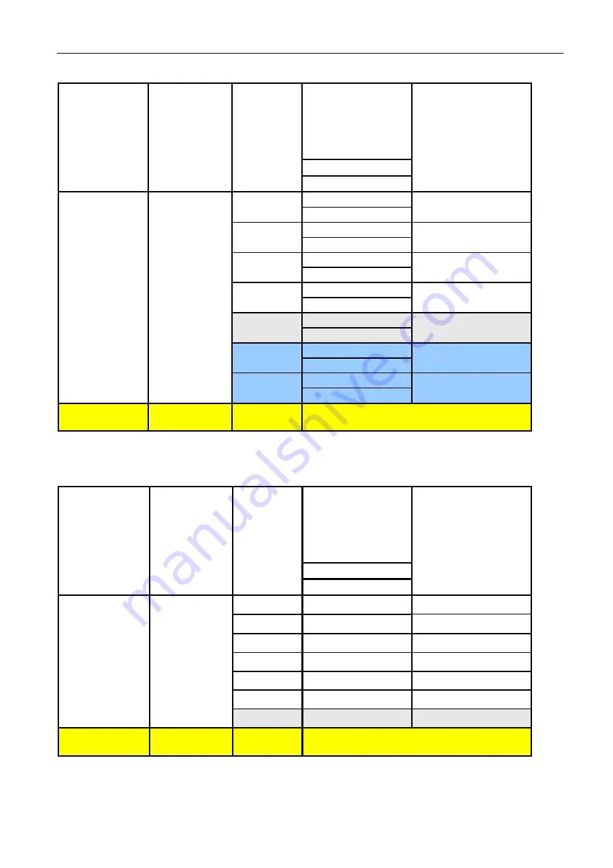
Table 1 –  Operating flow rate of the fuel dispenser in relation on the fuel storage tanks parameters for 

hydraulic unit with Q

max

 = 40 dm

3

.min

-1

Geodetic 

suction head  

Hsg 

max 

[ m ] 

Inner diameter 

of suction 

piping 

DN 

min

 [ mm ] 

Length  

of suction 

piping 

L [ m ] 

Operating flow rate 

of the fuel 

disppenser without 

vapour recovery 

Q [ dm

3

. min

-1

]

 ±10 

%


Supposed loss in 
pressure in suction 
piping 

[ kPa ] 

Petrol 

Diesel oil 


40 


10 

40 

13 

40 

20 

40 

14 

40 

25 

35 

15 

40 

30 

35 

16 

40 

35 

30 

17 

35 

40 

25 

18 

35 

45 

20 

19 

30 

– 

50 

Greater 
than 35 

Pressure system – submersible pump in the 

tank 


 Table 2 – Operating flow rate of the fuel dispenser in relation on the fuel storage  tanks parameters           

for hydraulic unit with Q

max

 = 80 dm

3

.min

-1


Geodetic 

suction head  

Hsg 

max 

[ m ] 

Inner 

diameter of 

suction piping                  

DN 

min

 [ mm ] 

Length  

of suction 

piping 

L [ m ] 

Operating flow rate 

of the fuel 

disppenser without 

vapour recovery 

Q [ dm

3

. min

-1

]

 ±10 

%


Supposed loss in 
pressure in suction 
piping 

[ kPa ] 

Petrol 

Diesel oil 


50 

10 

80 

14 

20 

80 

15 

25 

80 

16 

30 

75 

17 

35 

75 

18 

40 

70 

19 

45 

65 

20 

– 

50 

Greater 
than 45 

Pressure system – submersible pump in the 

tank 


Summary of Contents for MAJOR V-line 46 Series

Page 1: ...1 F 420 516 519 102 sales adastsystems cz www adastsystems cz OÚ 003 2005 MSS A XI 2018 USER S MANUAL Instructions for Operation Maintenance and Installation Multi product fuel Dispenser operating by Suction or Pressure Pumping System MAJOR V line 46xx xxx V line 47xx xxx ...

Page 2: ......

Page 3: ...nic counter 26 7 3 Restart of the dispenser and electronic counter after power failure and voltage drop 26 8 ATTENDANCE 26 9 DISPENSER OPERATION 27 9 1 Dispensing with preselection 27 9 2 Description of the preselection function 27 10 FUNCTIONS OF KL MANINF MANAGER AND KL SERINF SERVICE KEYBOARDS 27 10 1 Manual setting of unit prices 28 10 2 Setting of unit price values from the control system in ...

Page 4: ...4 TRANSPORT 34 14 1 Transport of V line 46xx xxx 47xx xxx fuel dispenser and its putting on the base frame 34 15 DISPENSER INSTALLATION 36 15 1 Hydraulic part 36 15 2 Wiring 39 16 PACKING AND STORAGE 40 16 1 Packing 40 16 2 Storage 40 17 GUARANTEE AND CLAIMING 40 18 SPARE PARTS CATALOGUE 41 19 ACCESSORIES 41 20 DOCUMENTATION DELIVERED 41 21 ENCLOSURES 42 ...

Page 5: ...dle the equipment b Check the dispenser delivery completeness and inform the manufacturer immediately in case of any discrepancies or damage c The dispenser shall be stored in a dry and protected room before it is installed at the filling station d Prior to dispenser installation check the completeness of the filling station technology according to the valid design check the connecting dimensions ...

Page 6: ...gated for the operation in environment specified by II2G IIAT3 symbols shown on the dispenser plate Considering operation safety in environs with explosion danger the dispensers have been EC type examination certification according to the annex III of the Directive 2014 34 EU ATEX by an authorised body FTZÚ Pikartská 7 716 07 Ostrava Radvanice Notified body no 1026 EC Type Examination Certificate ...

Page 7: ...apor Equipment recuperate consultation draft petrol vapor displaced from the fuel tank of a motor vehicle during refueling and carrying gasoline vapors to the storage tank at the service station IMPORTANT NOTE Terms of service stations and control petrol vapor recovery system stage II is drived by the Directive 2009 126 EC of the European Parliament and Council and the relevant national legal regu...

Page 8: ...during maintenance or filling fuel In case skin comes to contact with fuel or impurities wash the spot with water and soap as soon as possible When eyes come to contact medical treatment is necessary Do not inhale harmful vapours when filling fuel 4 BASIC DESCRIPTION 4 1 Design of dispensers Skeleton a self supporting structure consisting of parts with high anticorrosive resistance The base of the...

Page 9: ... dispensers of the V line H R 46xx xxx V line H R 47xx xxx type series are supposed to be installed at the following filling stations V line H R 46xx xxx for filling stations with the suction system of pumping V line H R 47xx xxx for filling stations with central pressure distribution system 4 2 Hydraulic system of the fuel dispenser The integrated hydraulic unit consists of a pumping monoblock wi...

Page 10: ...erates 2 x 100 impulses per 1 dm3 The meter is electronic calibrated by an el meter processor with the help of the service keyboard Meters are supplied with optional integrated magnetic pulse transmitter Eltomatic ME 01 05 type designation M 403 25P M 403 32P M 403 25EP M 403 32EP or with a magnetic pulse transmitter METRA MTX 075 or ADAST 40 type designation M 403 25P 1 M 403 32P 1 M 403 25EP 1 M...

Page 11: ... after calibration finish Displays LCD type with BACK LIGHT illumination LCD displays with BACK LIGHT DISPLAY BLD illumination are used especially for their good readability The duration of data holding on the display after supply voltage failure is 30 minutes at least Decimal point on BLD display devices is represented automatically in accordance with the setting of parameters Lighting LED diodes...

Page 12: ...apor by hydromechanical proportional valve integrated into nozzle Elaflex 2 System VRC E Vapour Recovery Control Electronic control the flow of vapor through the proportional solenoid valve directly controlled by an electronic control unit dispenser single chip microcontroller electronic counter 3 System VRC M VRMS System VRC M with automatic control system VRMS Vapour Recovery Monitoring System V...

Page 13: ...the storage tank usually from the lowest octane gasoline Optimal flow of vapor is dynamically regulated by proportional hydromechanical valve depending on the actual flow of liquid gasoline nozzle Proper function of vapor recovery is indicated by shining symbol of two arrows Fig 9 on the display of electronic counter on the appropriate side of the dispenser Pic 3 Pic 4 System VRC non functional Sy...

Page 14: ...8 pos 7 Inside of coaxial interpiece pos 6 pairs are guided to a flexible connecting pipe pos 4 then proceed to the proportional solenoid valve pos 4 From the proportional valve through conecting flexible pipe pos 3 guided to piston vakuum pump pos 2 From the piston pump pos 2 are drawn through flexible pipe to outgoing pipe of petrol vapours pos 1 connected to imide space of storage tank usually ...

Page 15: ... M 16 x 1 5 for connection to outgoing pipe into storage tank 2 Piston vacuum pump 3 Flexible connecting pipe between the vacuum pump and measuring probe VAPORIX Flow 4 Flexible connecting pipe between measuring probe VAPORIX Flow and coaxial interpiece 5 Coaxial interpiece for connecting of coaxial delivery hose 6 Coaxial delivery hose 7 Delivery nozzle for vapour recovery with integrated hydrome...

Page 16: ...e VAPORIX Flow 2 Terminal block for connection of input power 3 Output communication line for connecting of unit VAPORIX Master 4 Pulse inlet from the module VAP of electronic counter 5 Out A B 1 NC contact STOP red diode 6 Out A B 2 NO contact ALARM orange diode 7 Indicating LED diode for side A 8 Indicating LED diode for side B Pic 8 ...

Page 17: ...tgoing pipe into storage tank 2 Piston vacuum pump 3 Flexible connecting pipe between the vacuum pump and electromagnetic proportional valve 4 Regulation electromagnetic proportional valve 5 Flexible connecting pipe between the vacuum pump and measuring probe VAPORIX Flow 6 Flexible connecting pipe between the measuring probe VAPORIX Flow and coaxial interpiece 7 Coaxial interpiece for conection o...

Page 18: ...USER S MANUAL V line 46xx 47xx 14 Pic 15 Pic 16 ...

Page 19: ...USER S MANUAL V line 46xx 47xx 15 Pic 10 Scheme of inputs and outlets of the unit VAPORIX Control ...

Page 20: ...hich compares these values with the values given volume of liquid gasoline from the transmitted pulse output electronic counter Item 8 into the VAPORIX Control Connection Figure 6 Item 4 The operational statue of the system can notify the operator VRMS at the kiosk station via electronic unit VAPORIX Master which is usually located near the pumping station control system POS VAPORIX Control Units ...

Page 21: ...very system on the drive VRC Control VAPORIX indicated by blinking one tri color LEDs green orange red In the event that the compared values match which means that the variation in the actual flow rate measured by the system VAPORIX set flow rate to the proportional vapour recovery valve are in the range from 85 to 115 of the exhaust vapor volumetric given liquid gasoline to drive VAPORIX Control ...

Page 22: ...RANGE warning signal the vapor flow values are outside the specified tolerance System status indication VRMS on the fuel dispenser On the front cover mask the electronics housing DIODE FLASHING ORANGE warning signal pos 1 Pic 13 The fault in the revelant system must be fixed by specialised service worker within a period of 7 days 168 hod 4 VRC system works out of setled tolerance permanent fault m...

Page 23: ...7 Design with heating of the electronic case On the special customer s requirement the fuel dispenser can be delivered with heating of electronic case by heater 250 VA For feeding of the heating is used an individual cable see the enclosure no 25 5 TECHNICAL DATA 5 1 Basic parameters for the classical and alternative fuels with dynamic viscosity up to 20 mPa s Electronic counter ADPMPD T ADP1 T AD...

Page 24: ...CP IP Ethernet Average operating period of a repair too min 25 Average service life tz 5 years 1 Max flow rate Qmax 40 60 70 80 110 120 130 150 dm3 min 1 and min flow rate Qmin 4 5 10 15 dm3 min 1 extreme values of flow rate in which can be operate the measuring system of the fuel dispenser parameters Qmax and Qmin are given in a certificate about homologation of the meter type 2 Operating flow ra...

Page 25: ...ine 46xx V line 47xx Max flow rate Qmax 70 dm3 min 1 Min flow rate Qmin 5 dm3 min 1 Operating flow rate at at suction head 45 kPa Q 70 7 dm3 min 1 Min measured quantity MMQ 5 dm3 Max suction head 55 kPa for petrol 85 kPa for Diesel oil El motor 1 1 kW The module has been designed to dispense one sort of fuel from one filling point 5 1 5 Technical parameters one sided module Q 80 dm3 min 1 V line 4...

Page 26: ...0 dm3 Max suction head 85 kPa for Diesel oil El motor 2 x 1 1 kW The module has been designed to dispense one sort of fuel from one filling point 5 1 9 Technical parameters one sided module Q 130 dm3 min 1 with one meter M 403 32EP M 403 32P V line 46xx V line 47xx Max flow rate Qmax 130 dm3 min 1 Min flow rate Qmin 10 dm3 min 1 Operating flow rate at suction head 45 kPa dispensed from one nozzle ...

Page 27: ... from one filling point 5 1 12 Technical parameters one sided module Q 150 dm3 min 1 with two parallel working meters M 403 25EP M 403 25P V line 46xx V line 47xx Max flow rate Qmax 150 dm3 min 1 Min flow rate Qmin 10 dm3 min 1 Operating flow rate at suction head 45 kPa dispensed from one nozzle suction system Q 150 15 dm3 min 1 Operating flow rate by dispensing from one nozzle connection of subme...

Page 28: ...penser design V line 47xx xxx on the inner diameter and length of piping see the point no 15 in this instructions 5 2 1 Technical parameters one sided module Q 40 dm3 min 1 V line R 4701 010 2 40 OIL Max flow rate Qmax 40 dm3 min 1 Min flow rate Qmin 4 dm3 min 1 Operating flow rate by dispensing from one nozzle connection of submersible pump with min flow rate 40 dm3 min 1 with min dynamic operati...

Page 29: ...nser 4 Type See enclosure 38 and 39 5 Number of EC type examination certificate M TCM 141 07 4505 6 Accuracy class 0 5 7 Serial number and year of manufacture According to dispensers manufacturer files 8 Ambient temperature range TAmb C Ambient operating temperature according to version of the fuel dispenser 9 Liquid temperature range TLiq C 20 to 0 10 to 50 10 Mechanical class M 2 11 Electromagne...

Page 30: ...sed to attend the dispenser It is up to the customer s decision what fuel he is going to fill The electronic counter is activated by lifting the dispensing nozzle test of proper function of the counter automatic switching on of the pump and opening of electromagnetic valves are performed The customer can fill There is a condition to insert the dispensing nozzle adapter into a tank socket as deep a...

Page 31: ...ispensed is displayed on the price display In case of invalid option deselect it by the reset key 1 b Preselect the required quantity to be dispensed according the volume by keys identified 5 litres and 10 litres in arbitrary sequence up to the required volume level The preselected volume to be dispensed is displayed on the volume display In case of invalid option deselect it by the reset key 2 Th...

Page 32: ...fuel product are set by means of the KL MANINF manager keyboard or the KL SERINF service keyboard 1 The user can enter the setting mode of unit prices by depressing the 0 key 2 In the setting mode of unit prices the number of side for which the unit price is being set 1 A side 2 B side is displayed on the first line of displays i e on the line of total price the number of nozzle for which the unit...

Page 33: ... to the volume totalizer displays of the next dispensing nozzles by repeated depressing the key or by lifting the relevant nozzle as well as the transition to the price totalizer displays of the next dispensing nozzles by repeated depressing the key or by lifting the relevant nozzle 6 Terminate the scanning of electronic totalizers by depressing the 0 key and in case the thermal and electronic cal...

Page 34: ...sing a million dm3 through the dispenser or once per a year at least check the greasing condition of the pump ball bearing If necessary grease the bearing by LITOL 24 lubricating grease or a grease of similar quality Checking should be performed after dismantling the pump belt pulley Possible defects of the monoblock clogged filter exchange the filtering sleeve faulty venting air bubbles appear in...

Page 35: ...ing the preselected volume The first stage partially closes the flow to approximately 10 of the flow rate just before the set value is achieved The second stage closes the flow completely The operation of the two level stage closing of the valve shall be followed and prospective defect shall be repaired in time The closing and the throttling functions are eliminated in the service mode The repair ...

Page 36: ...r and lifting it upwards on hinges The cover lifted is screwed by means of the cover holder in the upper position Any handling the electric and electronic parts may only be carried out by a specialist who is responsible for the safety of the equipment The IP 54 protection may not be affected during the counter case handling It is necessary to check the gasket prior to remounting the cover Damaged ...

Page 37: ...ant and restoration of preservative coating is also recommended after more extensive surface staining by fuels Recommended time interval for the maintenance of stainless body parts ATTENTION DO NOT WASH STAINLESS STEEL SHEETS BY WATER OR EVEN SURFACTANT Recommended procedure for stainless steel sheets Washing of parts by thorough cleaning of salt residues dust and grease followed by the renewal of...

Page 38: ...ct but is not responsible for the transport itself It is generally accepted that the dispenser shall be shipped properly boxed and always fixed to the frame The dispenser should be protected against damage of covering and painting displacement and rolling over on the means of transport A special frame with holes for forklift is used for the of the dispenser All manipulation and transport have to b...

Page 39: ... in the same way as for the item 1 and lower the dispenser on it see Fig 4 Release the tilted support item 1 in the same way and after the same procedure for item 2 lower the dispenser on the base frame to the final position see Fig 5 and 6 Fasten the dispenser to the base frame by means of bolts Transport of V line 46xx xxx 47xx xxx dispensers ...

Page 40: ...eflon tape and pressure tested The vapour exhaust recovery will be connected to the T or L pieces part of the dispenser delivery by means of M 16 x 1 5 cap nuts of the connecting piping special hose The T or L piece is screwed through a reducer on the draw off pipe DN 25 with external thread G 1 and sealed similarly to suction flanges Leakage is difficult to identify after the dispenser seating Th...

Page 41: ...4 40 25 35 15 40 30 35 16 40 35 30 17 35 40 25 18 35 45 20 19 30 50 Greater than 35 Pressure system submersible pump in the tank Table 2 Operating flow rate of the fuel dispenser in relation on the fuel storage tanks parameters for hydraulic unit with Qmax 80 dm3 min 1 Geodetic suction head Hsg max m Inner diameter of suction piping DN min mm Length of suction piping L m Operating flow rate of the...

Page 42: ...rior of the dispenser and consequently into its close area in case of the leakage or blocking of the check valve flap when the dispenser is out of operation it is necessary to connect the separator outlet of the pumping monoblock to the storage tank This connection shall be carried out by means of a tube OT min 8 x 1 DN 6 connected to the tube adapter DN 6 The tube adapter with the gasket is screw...

Page 43: ...terminals resistant to combustion liquid effect can be used in the shafts under dispensers The cable bushings can always be used for one cable only ATTENTION Emergency switching off It shall be enabled to switch off the filling equipment from one point which is accessible anytime The electric equipment situated in the explosion hazard area can be switched off by means of the emergency breaker loca...

Page 44: ...ludge water or other impurities from tanks fuel storage tanks shall be ensured entirely It is carried out by means of decantation equipment which shall be a part of the filling station equipment If the manufacturer carrying out guarantee repairs identifies excessive quantity of impurities in the hydraulic system the complaint will not be accepted and expenses will be charged to the user Claims wil...

Page 45: ... and operation of the permanent feeding source UPS UPS Uninterruptible Power Supply 18 SPARE PARTS CATALOGUE Spare parts catalogues of the dispenser are supplied to service organisations The user can request the spare part catalogues from the manufacturer 19 ACCESSORIES Parts of the dispenser delivery Transporting and manipulation supports Set for hydraulic system connection to V line 46xx xxx dis...

Page 46: ... Installation dimensions of V line H and V line R 47xx xxx dispensers with drip pan Encl No 15 Installation dimensions of V line H and V line R 47xx xxx dispensers without drip pan Encl No 16 Installation dimensions of V line H and V line R 47xx xxx dispensers without drip pan Encl No 17 Installation dimensions of V line H and V line R 47xx xxx dispensers Connection of the dispenser module V line ...

Page 47: ...tral pressure system A location scheme official marks on ADP1 L electronic calculator Encl No 33 A location scheme official marks on ADP1 T а ADP2 T L electronic calculator A location scheme official marks on ADPMPDx T a ADPMPDx T PWM electronic calculator Encl No 34 A location scheme verification marks on electromagnetic total counter for single sided fuel dispensers A location scheme verificatio...

Page 48: ...in dimensions of dispensers V line H 46xx xxx V line H 47xx xxx series V line H 4601 xxx V line H 4602 xxx V line H 4603 xxx V line H 4701 xxx V line H 4702 xxx V line H 4703 xxx V line H 4604 xxx V line H 4605 xxx V line H 4704 xxx V line H 4705 xxx ...

Page 49: ...USER S MANUAL V line 46xx 47xx Enclosure No 2 Main dimensions of dispensers V line R 46xx xxx V line R 47xx xxx series ...

Page 50: ...USER S MANUAL V line 46xx 47xx Enclosure No 3 Main dimensions of dispensers V line R 46xx xxx CA R 47xx xxx CA series ...

Page 51: ...USER S MANUAL V line 46xx 47xx Enclosure No 4 View of dispensers V line H 46xx xxx V line H 47xx xxx series View of dispensers V line R 46xx xxx V line R 47xx xxx series ...

Page 52: ...USER S MANUAL V line 46xx 47xx Enclosure No 5 View of dispensers V line R 47xx xxx OIL series ...

Page 53: ...ition of dispensing nozzle during filling The dispensing nozzle is diverted from the horizontal plane drawn position The ball prevents from air passing the fuel does not flow through 3 Due to different executions of inlet fuel tank sockets it is necessary to find an optimum position of the dispensing nozzle when the fuel still flows through The flow can be broken when the fuel flow from the dispen...

Page 54: ...USER S MANUAL V line 46xx 47xx Enclosure No 7 ...

Page 55: ...USER S MANUAL V line 46xx 47xx Enclosure No 8 Installation dimensions of V line H and V line R 46xx xxx dispensers with drip pan ...

Page 56: ...USER S MANUAL V line 46xx 47xx Enclosure No 9 Installation dimensions of V line H and V line R 46xx xxx dispensers with drip pan ...

Page 57: ...USER S MANUAL V line 46xx 47xx Enclosure No 10 Installation dimensions of V line H and V line R 46xx xxx dispensers without drip pan ...

Page 58: ...USER S MANUAL V line 46xx 47xx Enclosure No 11 Installation dimensions of V line H and V line R 46xx xxx dispensers without drip pan ...

Page 59: ...USER S MANUAL V line 46xx 47xx Enclosure No 12 Installation dimensions of V line H and V line R 46xx xxx dispensers ...

Page 60: ...USER S MANUAL V line 46xx 47xx Enclosure No 13 Installation dimensions of V line H and V line R 47xx xxx dispensers with drip pan ...

Page 61: ...USER S MANUAL V line 46xx 47xx Enclosure No 14 Installation dimensions of V line H and V line R 47xx xxx dispensers with drip pan ...

Page 62: ...USER S MANUAL V line 46xx 47xx Enclosure No 15 Installation dimensions of V line H and V line R 47xx xxx dispensers without drip pan ...

Page 63: ...USER S MANUAL V line 46xx 47xx Enclosure No 16 Installation dimensions of V line H and V line R 47xx xxx dispensers without drip pan ...

Page 64: ...USER S MANUAL V line 46xx 47xx Enclosure No 17 Installation dimensions of V line H and V line R 47xx xxx dispensers Connection of the dispenser module V line 47xx xxx ...

Page 65: ...nal UPS output must be provided 9 To the stabilized voltage circuits no other consumers that are not a part of prescribed technology can be connected 10 Therefore the sockets of stabilized voltage must be marked by the description e g Control system feeding 11 The protection of input circuits of UPS must be dimensioned so that UPS feed outage and total battery discharge did not occur under standar...

Page 66: ...USER S MANUAL V line 46xx 47xx Enclosure No 19 Connection of dispenser V line 46xx xxx to the filling station switchboard ...

Page 67: ...USER S MANUAL V line 46xx 47xx Enclosure No 20 Connection of dispenser V line 46xx xxx with satellite to the filling station switchboard ...

Page 68: ...USER S MANUAL V line 46xx 47xx Enclosure No 21 Connection of dispenser V line 47xx xxx with vapour recovery system to the filling station switchboard ...

Page 69: ...USER S MANUAL V line 46xx 47xx Enclosure No 22 Connection of dispenser V line 47xx xxx without vapour recovery system to the filling station switchboard ...

Page 70: ...USER S MANUAL V line 46xx 47xx Enclosure No 23 Connection of dispenser V line 47xx xxx with satellite and vapour recovery system to the filling station switchboard ...

Page 71: ...USER S MANUAL V line 46xx 47xx Enclosure No 24 Connection of dispenser V line 47xx xxx with satellite without vapour recovery system to the filling station switchboard ...

Page 72: ...USER S MANUAL V line 46xx 47xx Enclosure No 25 Connection of the fuel dispenser heating to the filling station switchboard valid only for the fuel dispenser with electronic case heating ...

Page 73: ... of the magnetic pulse transmitter ME 01 05 ME01 05 05 and MTX 075 to the electronic counter ADP1 L connector X1 Magnetic pulse transmitter ME 01 05 Magnetic pulse transmitter ME 01 05 05 Magnetic pulse transmitter MTX 075 Magnetic pulse transmitter ADAST 40 ...

Page 74: ...USER S MANUAL V line 46xx 47xx Enclosure No 27 Connection of the magnetic pulse transmitter ME 01 05 ME01 05 05 and MTX 075 to the electronic counter ADP1 T ADP2 T connector X2 ...

Page 75: ...USER S MANUAL V line 46xx 47xx Enclosure No 28 Connection of the magnetic pulse transmitter ME 01 05 ME01 05 05 and MTX 075 to the electronic counter ADPMPDx T ADPMPDx T PWM connector X3 ...

Page 76: ...UAL V line 46xx 47xx Enclosure No 29 A location scheme official marks on the flowmeter M 403 25P for mechanical calibration A location scheme official marks on the flowmeter M 403 25P 1 for mechanical calibration ...

Page 77: ...AL V line 46xx 47xx Enclosure No 30 A location scheme official marks on the flowmeter M 403 xxEP for electronic calibration A location scheme official marks on the flowmeter M 403 xxEP 1 for electronic calibration ...

Page 78: ...AL V line 46xx 47xx Enclosure No 31 A location scheme official marks on the pumping unit P641 xxx 2 SS A location scheme official marks on the temperature sensor PT 100 Just if ATC conversion function is activated ...

Page 79: ...line 46xx 47xx Enclosure No 32 A location scheme marks official on the temperature sensor PT 100 fuel dispenser connected to the central pressure system A location scheme official marks on ADP1 L electronic calculator ...

Page 80: ...ER S MANUAL V line 46xx 47xx Enclosure No 33 A location scheme official marks on ADP1 T а ADP2 T L electronic calculator A location scheme official marks on ADPMPDx T a ADPMPDx T PWM electronic calculator ...

Page 81: ...xx 47xx Enclosure No 34 A location scheme verification marks on electromagnetic total counter for single sided fuel dispensers A location scheme verification marks on electromagnetic total counter for multiproduct dispensers ...

Page 82: ...USER S MANUAL V line 46xx 47xx Enclosure No 35 A location scheme verification marks on electromagnetic total counter case version 2017 ...

Page 83: ... the coaxial hose and nozzle with vapour recovery for dispensing petrol the internal space popeline for vapory reovery system proportional valve and vacuum pump ZONE 0 The electronic counter casing anchored to the dispenser hose module column is separated by the barrier type 1 according to EN 13617 1 protection degree IP67 according to EN 60529 The casing is designed with protection degree IP67 IP...

Page 84: ...coaxial hose and nozzle with vapour recovery for dispensing petrol the internal space popeline for vapory reovery system proportional valve and vacuum pump ZONE 0 The electronic counter casing anchored to the dispenser hose module column is separated by the barrier type 1 according to EN 13617 1 protection degree IP67 according to EN 60529 The casing is designed with protection degree IP67 IP54 ca...

Page 85: ...USER S MANUAL V line 46xx 47xx Enclosure No 38 The model marking on the dispenser V line 46xx xxx 47xx xxx rating plate ...

Page 86: ...USER S MANUAL V line 46xx 47xx Enclosure No 39 The model marking on the dispenser V line 46xx xxx CA 47xx xxx CA rating plate ...

Reviews: