background image


2016.05.16 

Adaptrum©  

P a g e  

53 | 64 

[email protected]


All Rights Reserved Worldwide


2016 

Adaptrum ACRS2.0 Quick Start Guide (International) 

Configuration 

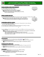
To remote update CLIENT configuration, in the BASE GUI, go to the Link tab, Link List View sub-tab. 

Right-click on desired target name in Notes column; if there’s no name under Notes, right-click in the 
empty space (and add System Notes when the Remote Config window opens). 

Right-click opens a pop-up; 

select the desired operation, e.g. Update Configuration.


This opens the Remote Config window 


Edit any/all fields as desired.  See 

MAC Address Specification

 discussion to modify MAC Filter Table. 

Make sure Auto Channel is checked so unit will auto-connect after reboot.


Save Settings to Remote and Reboot    

Make sur

Auto Update

 is not enabled when you do this.


Note: If the AdaptrumTVBD GUI is running on the target CLIENT, it will need to be restarted.


A

P

P

EN

D

IX


Summary of Contents for ACRS 2.0

Page 1: ...Rev 2016 05 16 Adaptrum ACRS2 0 Quick Start Guide International Cognitive Radio Systems ACRS2 0 Quick Start Guide International Manual ...

Page 2: ...diate radio frequency energy and if not installed and used in accordance with the instructions may cause harmful interference to radio communications If this equipment does cause harmful interference to radio or television reception which can be determined by turning the equipment off and on the user is encouraged to try to correct the interference by one or more of the following measures 1 Reorie...

Page 3: ...Notes 8 INVENTORY 9 BASE 10 Setup 10 Channel Selection 13 Start Service 15 CLIENT 16 Setup 16 Channel Selection 17 MAC Address Specification 19 Link Status Check 20 INSTALLATION 21 Radio Mounting 21 Hardware 21 Radio Unit 21 Ethernet cable 22 Antenna Orientation 25 Basic 25 Indoor Testing 25 Multiple CLIENTs 25 Collocation 26 Relay 26 Antenna Mounting 27 Hardware 27 Vertical Pole 28 Horizontal Pol...

Page 4: ...ns 39 Log Tab 40 Link Tab 41 System Information Tab 43 Diagnostics Tab 44 Database Tab 46 Installation Tab 48 Device Channel pane 50 Updating Firmware Local 51 Remote Update 52 Firmware 52 Configuration 53 Log File reading 54 Remote 54 Local 54 Checking Link Status 55 LED Interpretation 56 Spectrum Scan Channel Quality 56 8MHz Channels 57 Modulation Rates 58 Mechanical Dimensions 59 Markings 60 Sy...

Page 5: ...re 27 Figure 14 Fracarro Antenna Mount on Vertical Pole bolt head positioning 28 Figure 15 Fracarro Antenna Mount on Vertical Pole 28 Figure 16 Fracarro Antenna Mount on Horizontal Pole 29 Figure 17 Fracarro Antenna Cable SMA Connector Through Weather Sleeve 30 Figure 18 Fracarro Antenna F type connector 30 Figure 19 Antenna Cable Secured to Antenna and ACRS 30 Figure 20 Default GUI screenshot Lin...

Page 6: ... 8 Diagnostics Field Descriptions 45 Table 9 BASE Database Field Descriptions 46 Table 10 CLIENT Database Field Descriptions 47 Table 11 BASE Installation Field Descriptions 48 Table 12 CLIENT Installation Field Descriptions 49 Table 13 Device Channel pane Field Descriptions 50 Table 13 LED Interpretation table 56 Table 14 8MHz Channel Frequency List 57 Table 15 Modulation Rate Selection List 58 D...

Page 7: ...rein you will need the following items Required Items 2 laptops 1 ACRS2 0 unit BASE International configuration 1 ACRS2 0 unit CLIENT International configuration 2 antennas LP45F 2 PoEs 1 switch power adapter 1 router power adapter 2 International power cords 5 Ethernet cables 4 for PoEs 1 to internet 2 antenna mounting hardware wrench and or socket set to fasten ACRS antenna mounts extension cord...

Page 8: ...oading See Figure 12 Multiple Units Make sure to change unit IP addresses when installing multiple units All BASEs are delivered with default address 169 254 0 8 all CLIENTs are delivered with default address 169 254 0 9 Remote Updates CLIENTs MUST BE updated before the BASE BASE must Start Service and link with CLIENT must be established BASE Auto Update must be off but Update Status must be perf...

Page 9: ...label on rear 2 ACRS to antenna cable 3 Ethernet cable weather resistant boot 4 PoE 5 ACRS mounting bracket 6 U bolts 2 7 bracket to pole mounting hardware 6 each nuts split washers flat washers 8 ACRS to bracket mounting hardware 6 each Philips head screws split washers flat washers 9 International power cord 10 contents sheet Be sure to compare the contents of the box with the enclosed Contents ...

Page 10: ...to BASE thru PoE Wait for the Ready LED configuration 30 seconds plus 5 seconds Launch AdaptrumTVBD Allow program to make changes In the pop up if necessary select an Ethernet Adapter then pull down TVBD IP choices BASE unit should appear in the pull down list if it doesn t ensure laptop wifi is disabled disconnected and LAN IP address is on the same subnet select auto discovered BASE unit Note no...

Page 11: ...ernational BASE units will be identified in the GUI banner as follows Change to System Information tab Verify Radio Software Version red highlight as of this printing latest G 0 9 99 if not refer to Updating Firmware Appendix Verify GUI Version blue highlight as of this printing latest 3 6 0 33 if not download latest executable and see Installing Software Appendix BASE SETUP ...

Page 12: ...de International Change to Database tab Enter LAT LNG AGL yellow highlight for the BASE Change to Installation tab Recommended Enter System Notes orange highlight e g a unique label identifying this unit Edit IP address settings purple highlight as desired make note of them Save All Settings to Target and Reboot BASE SETUP ...

Page 13: ...D configuration Restart AdaptrumTVBD In the pop up pull down TVBD IP choices select BASE unit Connect After GUI opens to Log tab change to Database tab Verify the unit is using the manual database In the Device Channel pane open the Channel Unset pull down Select any available channel for now You will be able to change this later after the spectrum scan e g channel 21 This enables diagnostics to s...

Page 14: ...ectrum scan on all channels Measure All Channel Quality Sort results by Channel Quality column green good yellow marginal orange avoid not recommended red bad do not use Note If nearly all channels show good green quality ensure that the antenna cable is properly connected Note the Channel_Id with highest quality lowest Channel Quality number in this example channel 21 BASE SETUP ...

Page 15: ...o be used after reboot recommended Return to the Installation tab Save All Settings To Target and Reboot Start Service Re launch AdaptrumTVBD In the pop up pull down TVBD IP choices select BASE unit Connect If Persistent Channel was checked the unit will auto start service the Start Service button will be gray and the Transmit Link LED 3rd from left will be illuminated blue Otherwise if the Persis...

Page 16: ...nnect laptop wifi Setup apparatus for initialization Connect cable from laptop to CLIENT thru PoE Wait for the Ready LED configuration 30 seconds plus 5 seconds Launch AdaptrumTVBD Allow program to make changes In the pop up pull down TVBD IP choices select auto discovered CLIENT unit Note non default TVBD appears as IP address serial number in parentheses first line in example above Connect PoE C...

Page 17: ...ide 2016 Adaptrum ACRS2 0 Quick Start Guide International GUI will open to the data Log tab International CLIENT units will be identified in the GUI banner as follows Change to Database tab Enter LAT LNG AGL yellow highlight for the CLIENT Channel Selection Click Select CLIENT SETUP ...

Page 18: ... two scenarios 1 the BASE channel is changed which would happen only if you manually change it 2 the CLIENT is between two BASEs one of which ceases operation in this case the CLIENT will begin a new channel search and auto discover the 2nd BASE assuming its channel is also specified below Close the Scan Channel List and click Update Now Observe Channel Search Success message for at least one chan...

Page 19: ...ddresses specified in the filter table default MAC shown Pull down MAC Address list green highlight Select MAC Address es to add in this example there is only one the CPE laptop Add This adds the selected MAC Address to the filtering table The default MAC address should be removed from the table Select the old default MAC Address Remove In the above example the Filter Table now contains a single M...

Page 20: ... Status Check Restart AdaptrumTVBD select CLIENT unit Connect After GUI opens check Auto Channel and wait for Channel Search Success on one of the selected channels Your CLIENT should now be linked with the BASE as indicated by the Link LED 3rd from left illuminated blue Now check the Link Status See Appendix Checking Link Status CLIENT SETUP ...

Page 21: ...t washers 1 bag ACRS to mounting plate hardware o 6 Philips head screws o 6 lock washers o 6 flat washers Ethernet cable weather boot Radio Unit It is recommended to mount the ACRS unit to the base plate before mounting the base plate to the pole as shown below The radio unit may be mounted on either a vertical or horizontal pole because the four ACRS to mounting plate holes form a square pattern ...

Page 22: ...n in Figure 2 and Figure 3 below Figure 2 ACRS bottom Ethernet RJ45 plug on the right Figure 3 Ethernet weather resistant boot The Ethernet weather resistant boot comes in two pieces as shown in Figure 4 a hard shell on the left and a soft shell on the right Figure 4 Ethernet weather resistant boot two pieces The soft shell has pre cut slits in the small end to facilitate passing the Ethernet cabl...

Page 23: ... the soft shell as shown in Figure 5 Ethernet cable with weather resistant boot assembly Next push the hard shell over the soft shell This forms the weather seal around the cable Figure 6 Ethernet cable with weather resistant boot assembled Ensure that there are no gaps between the soft and hard shells on the smaller end and that the cable is gripped securely by the soft shell Figure 7 Ethernet ca...

Page 24: ...r into the ACRS RJ 45 jack Figure 8 Ethernet connector in place Finally slide the weather boot into place ensure that the ridged portion of the soft shell is secured within the ridged metal edges of the ACRS enclosure Figure 9 Ethernet cable with weather resistant boot secured in ACRS enclosure This completes the Ethernet cable mounting to the unit FIELD INSTALLATION ...

Page 25: ...for indoor test point the antennas in opposite directions the reverse of what s shown above This helps reduce received power and avoid overloading Multiple CLIENTs For multiple CLIENTs CLIENT antennas should all be pointed directly at the BASE All CLIENT antennas should be within a 60 degree arc All CLIENT antennas should be within 30 degrees of the BASE antenna direction The BASE antenna directio...

Page 26: ...e on the same pole use the following distance guidelines Figure 12 Antenna Collocation Separation Distances Note Collocated antennas should be operated with 1 channel separation when possible Relay When setting up antennas to relay signals use the vertical stacking opposite direction collocation illustration above STACKING VERTICAL HORIZONTAL SAME OPPOSITE DIRECTION 48 48 Fin orientation 30 24 FIE...

Page 27: ...ware allows antennas to be mounted to either vertical or horizontal poles but in all cases the antenna fins should maintain vertical orientation The Fracarro LP45F antenna comes with the following kind of mounting hardware 2 brackets 2 bolts 2 10mm nuts Figure 13 Fracarro Antenna Mounting Hardware The bolt heads on right should be closest to the antenna mounting hardware FIELD INSTALLATION ...

Page 28: ...racarro Antenna Mount on Vertical Pole bolt head positioning Ensure the bolt s square collar is aligned with the insert as shown on left then slide the bold head into place as shown on right If the bolt head resists sliding into place try rotating it 90 degrees When properly seated the two bolts should appear as below left Figure 15 Fracarro Antenna Mount on Vertical Pole Then finish the assembly ...

Page 29: ...nt the antenna to a horizontal pole insert the bolts through the antenna base side holes as shown below left Make sure the bolts are fully seated as shown for the right bolt in the left figure Figure 16 Fracarro Antenna Mount on Horizontal Pole Then finish the assemble as shown above right Note Figure 16 shows how the hardware fastens not the final antenna fin orientation which should be vertical ...

Page 30: ...able SMA Connector Through Weather Sleeve Slide the weather boot to the other end of the cable to the F type connector below left then secure the F type connector to the antenna below right Figure 18 Fracarro Antenna F type connector Finish sliding the weather boot into its mating receptacle then turn to lock in place below left lastly secure the SMA connector to the ACRS unit and wrap with electr...

Page 31: ...ved Worldwide 2016 Adaptrum ACRS2 0 Quick Start Guide International APPENDIX Sync Laptop Time to Internet Left click on time system tray lower right of screen opens Clock Settings Change date and time Settings opens Date and Time pop up Change to Internet Time tab APPENDIX ...

Page 32: ...ll Rights Reserved Worldwide 2016 Adaptrum ACRS2 0 Quick Start Guide International On the Internet Time tab Change Settings Select a Server from the pull down Update Now OK OK Your laptop should now be synchronized with the specified internet server APPENDIX ...

Page 33: ...up process Because many laptops may be set to auto re enable wifi it may be insufficient to simply Disconnect using the pop up shown below Disconnect is insufficient To disable your wifi adapter use the Control panel Device Manager red highlight Locate your wireless network adapter right click to display pop up and select Disable To re enable wifi repeat the steps above but select Enable which wil...

Page 34: ... Reserved Worldwide 2016 Adaptrum ACRS2 0 Quick Start Guide International Installing Software Retrieve latest installer https www dropbox com sh acggl6kgbdlgfk2 AAAkvGFZf_5rGlXpfbk2X_eqa dl 0 e g Double click to execute The Setup Wizard opens Next Next Next APPENDIX ...

Page 35: ...2016 05 16 Adaptrum P a g e 35 64 support adaptrum com All Rights Reserved Worldwide 2016 Adaptrum ACRS2 0 Quick Start Guide International Install Wait Wait Read Accept Yes APPENDIX ...

Page 36: ...2016 05 16 Adaptrum P a g e 36 64 support adaptrum com All Rights Reserved Worldwide 2016 Adaptrum ACRS2 0 Quick Start Guide International Wait If you see this screen OK Next Read and Agree APPENDIX ...

Page 37: ...RS2 0 Quick Start Guide International Install Finish Finish You should now have the Adaptrum folder installed under Program Files and the AdaptrumTVBD icon on your desktop Note When updating software to ensure proper communication update both BASE and CLIENT control laptops to the same version APPENDIX ...

Page 38: ... working tab is selected The working pane has six tabs as follows Log default opening screen shows boot up and diagnostic messages shown above Link dynamic graphic view of link error rates with text listing of link parameters System Information general software hardware versions station database info channel list Diagnostics interactive channel quality measurement table Database device information...

Page 39: ... are found on the following GUI panes and tabs Note Fields in gray font are reserved for Adaptrum diagnostic use Exception Register Device is for use within regions governed by a spectrum oversight agency Table 1 GUI Functions Some additional functionality is found on various pop up windows notably Remote Update of CLIENTs via the BASE Link List View tab APPENDIX ...

Page 40: ...national Log Tab The AdaptrumTVBD GUI initially opens to the Log tab This screen provides information for Adaptrum diagnostics Figure 21 GUI screenshot Log tab FIELD DESCRIPTION 1 Log screen Software information and error message output log This information is intended solely for Adaptrum s use Table 2 Log tab Description APPENDIX ...

Page 41: ...lick to reset Uplink Error Packet Err Pkt count 4th parameter 4 Uplink Metrics connection rate Mbps PHY mode QAM QPSK PER packet errors Err Bit Error Rate BER Power dBm and Noise dBm 5 Client MAC Address indicates which CLIENT was selected from Link List Notes column 6 Expand button click to expand list of parameters reported fields 2 4 7 Mod Rate Select Click for modulation rate selection pull do...

Page 42: ... MAC CLIENT unit Serial Number MAC Address c Bandwidth D U Available Bandwidth Downlink Uplink in Mbps d PHY Mode D U PHY Mode Downlink Uplink e g QAM QPSK e PER D U Packet Error Rate Downlink Uplink in percent f Power D U Power Downlink Uplink in dBm g Noise D U Noise Downlink Uplink in dBm h SNR D U Signal to Noise ratio Downlink Uplink in dBm 30dB indicates a good link i Temperature CLIENT Temp...

Page 43: ...ber of hardware image 7 Temperature board temperature in degrees C updated by Device Channel pane fields 6 7 8 Link Test results packets sent received and Lost count results for Link Test field 9 9 Link Test initiates packet transmissions for test results found in field 8 10 Base Station MAC Base Station ID 11 Base Station Loc LAT LNG AGL of this BASE unit entered in Database tab field 2 12 Update...

Page 44: ...gnostics initiates capture of unit messages 6 Radio Hardware Ver version number of hardware image 7 Temperature board temperature in degrees C updated by Device Channel pane fields 6 7 8 Link Test results packets sent received and Lost count results for Link Test field 9 9 Link Test initiates packet transmissions for test results found in field 8 10 Base Station MAC Base Station ID 11 Base Station...

Page 45: ...ise and Interference lower is better 3 Channel List list of available channels constrained by Database tab field 9 4 Measure Available initiate quality measurement of selected available channels field 3 5 Measure All initiate quality measurement of all channels Table 8 Diagnostics Field Descriptions Channel Quality is indicated numerically lower numbers are better and by color bars interpreted as ...

Page 46: ...trant info to cognizant spectrum oversight agency 6 Device Info Loc same as field 1 7 Update Interval number of seconds between updates Device Channel fields 6 7 8 Hold Channel requires unit to retain channel even after timeout 9 Database specifies database source for constraining available channel list 1 10 BASE MAC address initially blank updated by button 14 11 BASE Channel List list of channel...

Page 47: ... channels available in field 17 and selectable by button 18 will be constrained by the spectrum oversight agency Figure 28 GUI screenshot CLIENT Database tab FIELD DESCRIPTION 2 Device Location Latitude Longitude Height of installed unit to be entered by user 17 Scan Channel Set set of channels selected by button 18 18 Select pulls down Scan Channel List to allow selection of desired channel set 1...

Page 48: ...1 System Notes user entered unique unit name highly recommended to fill this out 2 IP Address user entered IP address 3 Remote Server IP reserved 4 Select browser to navigate to desired firmware aip target file 5 file path name name of selected file must be a valid aip file 6 message window displays messages after update button 7 wait for ok to reboot message 7 Update Firmware initiates loading of...

Page 49: ...d 3 4 Select browser to navigate to desired firmware aip target file 5 file path name name of selected file must be a valid aip file 6 message window displays messages after update button 7 wait for ok to reboot message 7 Update Firmware initiates loading of selected file field 5 messages display in field 6 8 Save Reboot saves all changes causes unit to reboot puts changes into effect 9 MAC Addres...

Page 50: ...DESCRIPTION Fixed PPI PPII diagnostic functions reserved for Adaptrum s use only 1 Persistent Channel if checked causes unit to connect on selected channel field 3 after each reboot 2 Auto Channel if checked enables unit to scan through channel list BASE Database tab field 11 or CLIENT Database tab field 17 in search of finding the best channel 3 Channel Selector in manual mode allows user to sele...

Page 51: ...the default 169 254 0 8 for BASE 169 254 0 9 for CLIENT Retrieve latest firmware https www dropbox com sh acggl6kgbdlgfk2 AAAkvGFZf_5rGlXpfbk2X_eqa dl 0 e g Select to navigate to the desired aip file in the pop up Open GUI acknowledges valid aip file Update Firmware Wait for progress bar 5 seconds GUI acknowledges update wait for Save Reboot msg Save All Settings to Target and Reboot OK to close A...

Page 52: ...once Firmware Note 4 FIRST perform Remote Update Configuration record parameters To remote update CLIENT firmware in the BASE GUI go to the Link tab Link List View sub tab at bottom left Right click on desired target name in Notes column green highlight if there s no name under Notes right click in the empty space Right click opens a pop up select the desired operation e g Update Firmware This ope...

Page 53: ...he empty space and add System Notes when the Remote Config window opens Right click opens a pop up select the desired operation e g Update Configuration This opens the Remote Config window Edit any all fields as desired See MAC Address Specification discussion to modify MAC Filter Table Make sure Auto Channel is checked so unit will auto connect after reboot Save Settings to Remote and Reboot Make...

Page 54: ...s right click in the empty space Right click opens a pop up select the desired operation e g Read Log This will open aremote log in Notepad SaveAs to the file name of your choice and if desired re open with NotePad or equivalent editor for inspection Local To read the local BASE log file in the BASE GUI go to the System Information tab and click This will open a Notepad window as shown above SaveA...

Page 55: ...ENT will only paint Downlink graph green line and parameters green text Expected values for quality status indicators are as follows 64QAM excellent 16QAM OK Est Power 80db greater than 10 dBm separation between Power and Noise More link information may be obtained by clicking the onscreen expand button In the BASE GUI the Link Tab has a second tab the Link List View which will provide additional ...

Page 56: ...ooting N A ready not established transmitting linked 1 Marginal transmitting linked 1 OK transmitting linked 1 Good transmitting linked 1 Excellent searching 2 link lost 1 BASE transmitting CLIENT linked 2 CLIENT Spectrum Scan Channel Quality On the Diagnostics tab after clicking one of the Measure buttons Channel Quality is indicated numerically lower numbers are better and by color bars interpre...

Page 57: ...86 36 591 25 597 25 594 37 599 25 605 25 602 38 607 25 613 25 610 Band V Channel PAL I Vision MHz PAL I Sound MHz Centre MHz 39 615 25 621 25 618 40 623 25 629 25 626 41 631 25 637 25 634 42 639 25 645 25 642 43 647 25 653 25 650 44 655 25 661 25 658 45 663 25 669 25 666 46 671 25 677 25 674 47 679 25 685 25 682 48 687 25 693 25 690 49 695 25 701 25 698 50 703 25 709 25 706 51 711 25 717 25 714 52...

Page 58: ...ilable modulation rates either automatically selected by the unit or manually selected by the user via the Link Detail Chart modulation rate buttons Table 16 Modulation Rate Selection List Rate AutoRate QPSK1 2 QPSK2 3 QPSK3 4 QPSK5 6 16QAM1 2 16QAM2 3 16QAM3 4 16QAM5 6 64QAM1 2 64QAM2 3 64QAM3 4 64QAM5 6 Downlink Modulation Rate Select button Uplink Modulation Rate Select button APPENDIX ...

Page 59: ...2016 05 16 Adaptrum P a g e 59 64 support adaptrum com All Rights Reserved Worldwide 2016 Adaptrum ACRS2 0 Quick Start Guide International Mechanical Dimensions APPENDIX ...

Page 60: ...erved Worldwide 2016 Adaptrum ACRS2 0 Quick Start Guide International Markings On the unit s bottom side you will find the model red highlight and serial number green highlight The unit type BASE or CLIENT will be identified by a sticker on the back of the unit APPENDIX ...

Page 61: ...th external amplifier Channel Bandwidth Efficiency 94 Adjacent Channel Emission 55 dBc Receiver Sensitivity 6 MHz Channel Level SNR Data Throughput 98 dBm 3 5 dB 2 7 Mbps QPSK 1 2 90 dBm 11 5 dB 7 1 Mbps 16 QAM 2 3 81 dBm 20 5 dB 12 Mbps 64 QAM 3 4 Interface Specifications Integrated Antenna PCB Bowtie vertically polarized 0 dBi Optional external antenna connector SMA Female Data Control 10 100 Et...

Page 62: ...Quick Start Guide International GUI crash Should the GUI ungracefully terminate be sure to use the Task Manager to inspect the processes and use End Process to remove any unresponsive AdaptrumTVBD executable s When reporting such cases please note what lead up to the problem and if it is repeatable APPENDIX ...

Page 63: ...talling software 34 IP address es base 10 12 48 client Error Bookmark not defined 49 multiple 8 MAC address es base 46 base station 43 client 41 42 46 filter table 19 49 53 Persistent Channel base 15 50 remote configuration 53 firmware update 52 log read 54 updates 8 Serial Number in GUI 10 Er ror Bookmark not defined on label 60 SNR 42 55 61 software installation 34 System Notes base entry 48 cli...

Page 64: ...uide International CONTACT INFO Headquarters Phone 001 408 850 9996 x707 Email support_us adaptrum com Address Adaptrum Inc 2740 Zanker Road Suite 100 San Jose CA 95134 USA Africa email support_africa adaptrum com Asia email support_asia adaptrum com India email support_india adaptrum com UK email support_UK adaptrum com ...

Reviews: