background image

A

LPHA

X

PRESS

 2020 RGB F

RONT

 A

CCESS

 F

ULL

-M

ATRIX

 D

ISPLAYS

 S

IGN

 O

PERATION


AND

 M

AINTENANCE

 M

ANUAL

 (PN 1523610201 

REV

B

)

1-3

Introduction

1

S

YSTEM


OVERVIEW

VMS control system

The VMS control system used in the Variable Message Sign consists of the following components:

NTCIP compliant controller

LED display board/driver board

Sign controller

Display adapter

General operation

The NTCIP controller interfaces with the “Host” computer system, and communicates with the Host through a CAT5 Ethernet cable 
(standard) or an RS422 connection (option). Using this network connection or I/O port, the Host issues commands to, and requests 
status information from, the NTCIP controller. The controller monitors and controls the entire LED VMS system. Communication by the 
NTCIP controller to and from the Host is accomplished using industry standard 10/100 Ethernet communications circuitry and NTCIP 
protocol.

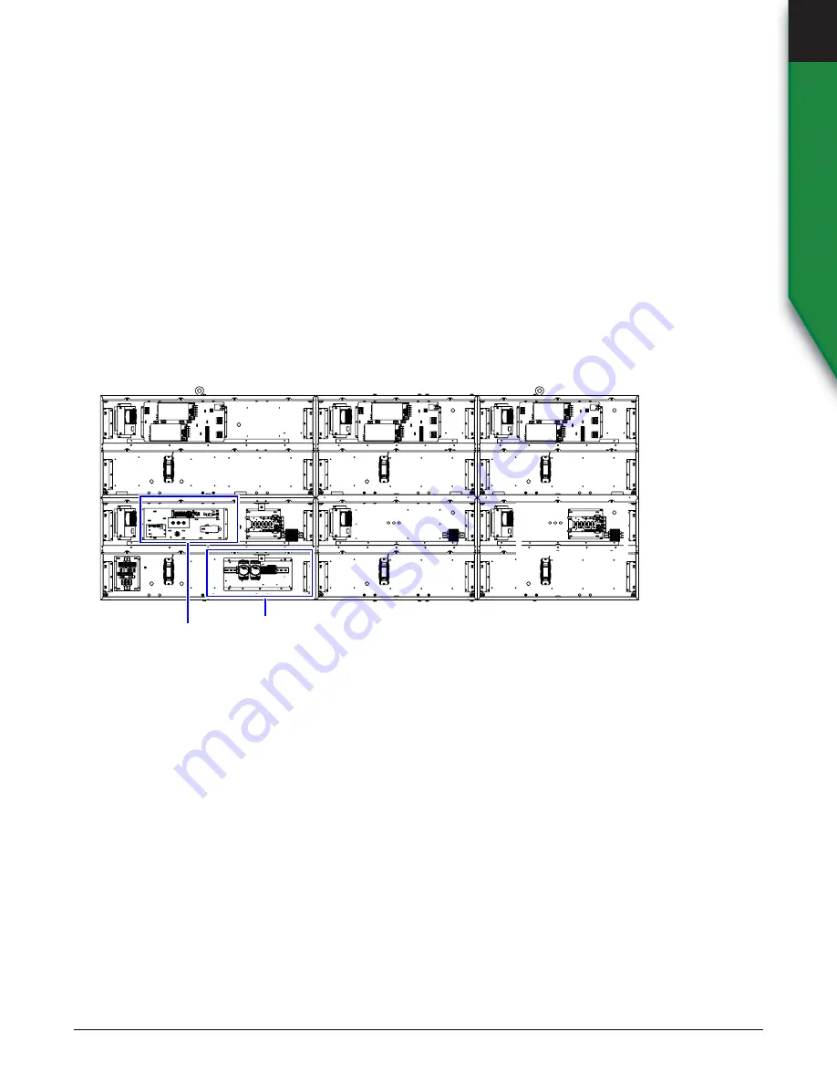
Placement of controllers

The controllers are located in the lower left modular case of all AlphaXpress 2020 sign configurations. Single row signs have a remote 
mounted controller.

LED brightness control system

The VMS is equipped with a brightness control system for the LEDs. The brightness control system ensures that the display is readable 
in all lighting conditions. The photocells are enclosed to protect them from the environment. Three photocells continually monitor the 
ambient light conditions. The photocell assembly is constructed in such a manner that adverse weather conditions (such as heavy 
snow) should have no effect on its performance. The main components of the brightness control system are the following:

Sign Controller

Light


sensor


assembly

General operation

The photocells are enclosed in an assembly designed to protect them from the environment. The photocells continuously monitor the 
ambient light conditions and the controller constantly polls the photocells for this information. The controller determines exactly how 
much ambient light is detected through the light-sensing photocells and sets the light output of the display module for it to adjust duty 
cycle of the LED current drive, thus dimming or brightening the LED modules according to the ambient light. (If the on time of the duty 
cycle is 50%, then the light output will be at 50%; if the on time of the duty cycle is 75%, then the light output will be at 75%, and so on.) 

Light sensor assembly mounting

Because the function of the photocells depends on ambient lighting, the light sensor assembly should be mounted in a location where 
it will receive maximum light exposure throughout the day. When choosing a mounting location for the light sensor assembly, make 
sure the assembly can receive ambient light on the front.

I/O plate

Sign controller plate

Summary of Contents for AlphaXpress 2020

Page 1: ...PART NUMBER 1523610201 REV B Sign Operation and Maintenance Manual AlphaXpress 2020 Front Access 20mm RGB Full Matrix Displays ...

Page 2: ...the FCC Rules These limits are designed to provide reasonable protection against harmful interference when the equipment is operated in a commercial environment This equipment generates uses and can radiate radio frequency energy and if not installed and used in accordance with the instruction manual may cause harmful interference to radio communications Operation of this equipment in a residentia...

Page 3: ...trol system 1 3 Environmental control system 1 4 Electrical system 1 4 General description 2 1 Exterior views 2 2 Sign interior 2 4 Components 2 5 Sign controller plate 2 5 I O plate 2 6 Power panel and power supplies 2 7 Display adapter 2 8 20mm LED module 2 9 Mechanical installation 3 1 Electrical installation 3 2 Physical inspection 4 1 Front lens cleaning outside of sign 4 1 Filter cleaning 4 ...

Page 4: ...9 Display adapter replacement 5 10 LED driver board replacement 5 12 Circulating fan replacement 5 13 Venting fan replacement 5 14 Filter replacement 5 15 Circuit breaker replacement 5 16 Surge suppressor replacement 5 18 Circuit breaker replacement 5 19 Surge suppressor replacement 5 20 Light sensor replacement 5 21 Short error status conversion A 1 Error status definitions A 3 Over temperature c...

Page 5: ... above mentioned systems in general terms for ease of understanding Referring to the drawings throughout this manual should help you to gain a general understanding of the LED Variable Message Sign system What is an LED LED based signs are one of the most versatile and visible display systems available We use a cluster of small LEDs to form a pixel The pixels are arranged in various matrices to fo...

Page 6: ...er reduces the light output to 0 The sign controller keeps the light output at 0 until the temperature falls below 76 C 133 F At this point the sign will be allowed to display at 50 brightness The NTCIP controller will report a Temperature Warning by raising bit 9 of the short error status The NTCIP controller will report a Critical Temperature Error by raising bit 11of the short error status Cond...

Page 7: ...The photocells are enclosed to protect them from the environment Three photocells continually monitor the ambient light conditions The photocell assembly is constructed in such a manner that adverse weather conditions such as heavy snow should have no effect on its performance The main components of the brightness control system are the following Sign Controller Light sensor assembly General opera...

Page 8: ...n the sign housings are the power supply plates containing two 24VDC switching redundant power sharing supplies The electronic power supplies convert the 120VAC to the required DC voltage to power all of the electronics in the sign DC power to the electronics is redundant and has a primary and secondary source of DC power Therefore failure of a single power supply will not impact sign performance ...

Page 9: ...201 REV B 2 1 Equipment Description 2 Equipment Description General description Serviceability Front access Pitch distance between each LED pixel 20mm Reference sales drawings for sign specifications Figure 2 1 Pitch is 20 mm LED pixel composed of 3 individual LED lamps 1 each of Red Blue Green 20mm ...

Page 10: ...emoval does not impact the integrity of the housing B SIGN MOUNTING STRUCTURE Used to mount display cases Horizontal Z bar entire length of sign for mounting to customer supplied structure vertical I beams are not supplied Varies depending on sign dimensions C LED MODULE Used to display content Item Name Description A LIFTING EYEBOLTS Used to lift the sign into position Can be removed after the si...

Page 11: ...NECTION Used to connect the light sensor Front top and rear connection C GROUND LUG Use to connect to an earth ground rod Sign must be grounded per NEC 250 and local electrical codes Never use the sign s ground lug to ground welding or any other installation equipment or the warranty will be void D PRIMARY POWER ENTRY E SECONDARY POWER ENTRY Used when required F ETHERNET COMMUNICATION ENTRY Water ...

Page 12: ...ker in the sign C SURGE SUPPRESSOR There is one surge suppressor at each power entry in the sign D CUSTOMER AC CONNECTION Customer AC connection E AC ENTRY Customer AC power connection when viewed from the front door F SIGN CONTROLLER PLATE Sign controller location G I O PLATE Contains all I O connections H VENTING FAN Prevent overheating of sign components I CIRCULATING FAN Internal recirculation...

Page 13: ...er plate Item Name Description A SIGN CONTROLLER Controls display and communicates status information to central communications B I O COM TERMINAL BLOCK Serial I O to display adapter C 485 HUB Serial communications distribution and 5V DC power to the sign controller D ETHERNET SURGE PROTECTOR Ethernet cable customer supplied plugs in to this location WINCE LICENSE D B A C ...

Page 14: ...OPERATION AND MAINTENANCE MANUAL PN 1523610201 REV B Equipment Description COMPONENTS 2 I O plate Item Name Description A I O MODULE Controls displays and communicates status information to central communications B TERMINAL BLOCKS Serial I O to display Adapter A ...

Page 15: ...ly plate B DC POWER FAIL TERMINAL BLOCK Power fail signal to controller C HI LIMIT TEMPERATURE SENSOR Hi Limit temperature warning for controller D DC SUPPLY OUTPUT E V 24VDC F N A DIODE MODULE Part number 30300003LFSP See Diode replacement on page 5 9 G V 24VDC DC output H DC SUPPLY OUTPUT I AC INPUT J N A SIGNAL CONNECTOR Used for remote control remote sense and power good signal K N A DC VOLTAG...

Page 16: ...ends on the size of the sign Refer to the sales drawings for locations in each sign size Item Name Description A DRIVER COMMUNICATION Each of the 6 outputs corresponds to a row of 9 LED modules B DVI OUT DVI signal routes to next display adapter in chain C 485 COMMUNICATION RS485 I O from sign controller and or next display adapter in chain D DVI IN DVI Signal from sign controller or from prior di...

Page 17: ...troller 1 via a ribbon cable B BIN LABEL Information on the intensity and wavelength of the LED lamps C P4 V1 Supplies power to the LED driver board D P6 Programming port for the LED driver board processor E STATUS 1 POWER On 24V supplied to LED driver board STATUS 2 FAULT On one or more bad LED lamps on the LED driver board if in normal operating mode STATUS 3 COMM On There is NO communication fr...

Page 18: ...THIS PAGE INTENTIONALLY BLANK 2 10 ALPHAXPRESS 2020 FRONT ACCESS FULL MATRIX DISPLAYS SIGN OPERATION AND MAINTENANCE MANUAL PN 1523610201 REV B ...

Page 19: ...ING WARNING Crush hazard Improperly lifting of a sign can create a crush hazard causing personal injury and damage the sign Only use the sign s lifting eyebolts to lift the sign Lift the sign evenly and level with no more than a 15 degree tilt RECOMMENDED Lifting bar Front view Use both eyebolts to lift the sign NOT RECOMMENDED Front view Not less than 60 Use both eyebolts to lift the sign ...

Page 20: ...REV B Installation ELECTRICAL INSTALLATION 3 Electrical installation AC wiring AC wiring for typical AlphaXpress 2020 WARNING Hazardous voltage Contact with high voltage may cause death or serious injury Always disconnect power to unit prior to service Line Neutral Ground Customer Wiring Sign circuit breakers AC ...

Page 21: ...V B 3 3 Installation 3 ELECTRICAL INSTALLATION Light sensor Plug the three light sensor cables into the light sensor ports on the back of the sign Network connection Plug the Ethernet cable into the external waterproof port on the back of the sign Light sensor ports External waterproof IP67 Ethernet connection ...

Page 22: ...THIS PAGE INTENTIONALLY BLANK 3 4 ALPHAXPRESS 2020 RGB FRONT ACCESS FULL MATRIX DISPLAYS SIGN OPERATION AND MAINTENANCE MANUAL PN 1523610201 REV B ...

Page 23: ...rational see Install a replacement venting fan on page 5 14 for details on testing fan operation Make sure the sign s drain holes are not plugged Front lens cleaning outside of sign Required materials Mild nonabrasive liquid detergent liquid glass cleaner Do not use solvents Use of solvents will damage the lens UV stabilizer Soft cloth or soft paper towels Cleaning procedure 1 Mix the detergent wi...

Page 24: ...THIS PAGE INTENTIONALLY BLANK 4 2 ALPHAXPRESS 2020 RGB FRONT ACCESS FULL MATRIX DISPLAYS SIGN OPERATION AND MAINTENANCE MANUAL PN 1523610201 REV B ...

Page 25: ...daptivedisplays com Opening a sign To open a sign 1 Remove power from the sign Note there may be more than one power source present 2 Using the hex tool PN 68117076 supplied turn the three or four 5 32 hex screw circled to open the front face frame Part name Page I O module replacement page 5 2 Sign controller page 5 3 Power supplies page 5 7 Diode module page 5 9 Display adapter page 5 10 LED dri...

Page 26: ... screw driver to detach BOTH green terminals from the module Note Do not remove the wires 4 Loosen both captive screws 5 Make note of address on module to ensure correct replacement part is used Install the replacement I O module 1 Install new module Note Make sure that the inputs DI are at the top 2 Reconnect the green terminals 3 Turn the breakers to the ON position to return power to the sign W...

Page 27: ...ign Note there may be more than one power source present 2 Open the sign See See Opening a sign on page 5 1 3 Turn the sign breaker to the OFF position Note there may be more than one breaker in a sign 4 Locate the controller board to be replaced 5 Disconnect all cables from the controller board to be replaced WARNING Hazardous voltage Contact with high voltage may cause death or serious injury Al...

Page 28: ...to the sign either serial or Ethernet connection 4 Enter the appropriate information for the connection method Name Description COMM PORT NUMBER The number of the serial port that serial communications will be routed through SERIAL ADDRESS The serial address of the sign being communicated with AlphaXpress signs are defaulted to address 1 unless otherwise specified TIMEOUT The amount of time allowe...

Page 29: ... sign The default controller IP address is 10 11 11 254 B UDP PORT The port number you wish to use Port 300 is typically available C TIMEOUT The amount of time allowed to pass before communications are marked as timed out and failed Longer timeouts can be helpful on slower or congested networks Name Description TYPE Indicates whether that IP address in use by the sign is statically as signed or as...

Page 30: ... to be central or local These designators are important when a local remote switch is utilized by a sign If a port is designated to be local communications over the port will be read only as long as the local remote switch is in the remote position If a port is designated to be central communications over the port will be read only as long as the local remote switch is in the local position Read o...

Page 31: ...e there may be more than one power source present 2 Open the sign See Opening a sign on page 5 1 3 Turn the sign breaker to the OFF position Note there may be more than one breaker in a sign 4 Locate the power supply to be replaced 5 Remove all wires from the power supply to be replaced DC connections V orange colored wire V violet colored wire Signal harness AC connections Line black wire Neutral...

Page 32: ...MENT 5 6 Loosen the two screws slide to the left or right and lift the power supply off of the plate Install a replacement power supply 1 Fasten the new power supply to the sign 2 Reconnect all the wires to the replacement power supply 3 Apply power and verify that the new power supply operates correctly 4 Close the sign 5 Return power to the sign Screws ...

Page 33: ...n the screws to disconnect the wiring from the diode module 6 Remove the nuts circled in Figure 5 7 securing the diode module to the power panel plate Install the replacement diode module 1 Apply thermal joint compound pn 67004105 to the bottom of the replacement diode module pn 30300003LFSP 2 Bolt the replacement diode module to the power panel plate Module 30300003LFSP will mount to 8 32x1 screw...

Page 34: ...ing a sign on page 5 1 3 Turn the sign breaker to the OFF position Note there may be more than one breaker in a sign 4 Disconnect in this order the DVI cables serial communication cables the driver communication cables and power supply 5 Loosen but do not remove the five mounting screws WARNING Hazardous voltage Contact with high voltage may cause death or serious injury Always disconnect power to...

Page 35: ... adapter One display adapter can control up to 54 display boards Each display adapter has unique DIP switch settings Settings vary depending location in the sign Hang the display adapter on the mounting screws Tighten the screws to secure the display adapter 2 Reconnect in this order the power cables DVI cables RS485 communication cables and the driver communication cables 3 Connect the power cabl...

Page 36: ...e cables from the power interface board Note Disconnect the cables in the order shown or damage to sign components may result 6 Remove the driver assembly and align the new driver assembly Make sure the new driver assembly has the same orientation as the original one Leave enough room to connect the cables in the next step Install the replacement LED driver board 1 Connect the cables to the power ...

Page 37: ...ght side of the fan 7 Remove the fan 8 Remove the fan wire carefully Install a replacement circulating fan 1 Replace fan wire taking care not to bend the pins 2 Place replacement fan in the bracket 3 Tighten the nuts to secure the fan 4 Return power to the sign Do not close the sign 5 Test the fan Use a heat gun directed at the fan thermostat to verify fan operation The thermostat must be heated t...

Page 38: ...sconnect the wire harness from the failed fan 6 Loosen the four screws holding the fan in place 7 Remove the fan Install a replacement venting fan 1 Reattach the fan wire to new fan taking care not to bend pins on fan 2 Reattach the fan to the bracket with four screws 3 Return power to the sign Do not close the sign 4 Test the fan Use a heat gun directed at the fan thermostat to verify fan operati...

Page 39: ...g the front display doors to loosen the screw on the ventilation housing 5 Rotate cover down as shown 6 Remove filter from hook and loop fastener 7 Insert new or cleaned filter close the ventilation housing and then secure with the hex key 8 Return power to the sign To replace a filter access the front serviceable filter 1 Remove power from the sign Note there may be more than one power source pre...

Page 40: ...it breaker 1 Remove power from the sign Note there may be more than one power source present 2 Open the sign See Opening a sign on page 5 1 3 Turn the sign breaker to the OFF position Note there may be more than one breaker in a sign 4 The circuit breaker is located next to the surge suppressor 5 Loose the screws at the top and bottom of the circuit breaker Disconnect the wires Circuit breaker Loo...

Page 41: ...elease tab under the circuit breaker Note yellow tab is not visible when circuit breaker is installed Install the replacement circuit breaker 1 Snap the replacement circuit breaker onto the mounting rail 2 Lock the circuit breaker to the rail by using a flathead screwdriver Push in and up 3 Reconnect the wires 4 Tighten the screws 5 Re install the display board Connect the power cables and then th...

Page 42: ...urce present 2 Open the sign See Opening a sign on page 5 1 3 Turn the sign breaker to the OFF position Note there may be more than one breaker in a sign 4 No tools are necessary to remove the surge suppressor 5 Using one hand firmly grip the top and bottom or the surge suppressor 6 Pull straight back to release the surge suppressor Install the replacement surge suppressor 1 Snap the new surge sup...

Page 43: ...er from the sign Note there may be more than one power source present 2 Remove the breaker panel cover 3 Turn the sign breaker to the OFF position 4 Remove wire from breaker 5 Remove breaker from panel Install the replacement circuit breaker 1 Insert replacement breaker onto the breaker panel 2 Reconnect the wires 3 Turn breaker to OFF position 4 Reinstall breaker panel cover 5 Apply power to the ...

Page 44: ...replacement Remove the surge suppressor 1 Remove power from the sign 2 Remove circuit breaker panel cover 3 Remove surge suppressor from breaker panel 4 Disconnect wire from surge suppressor Install the replacement surge suppressor 1 Reattach wire to surge suppressor 2 Install surge suppressor to breaker panel 3 Reinstall breaker panel to cover 4 Apply power to sign Surge suppressor ...

Page 45: ... sensor Use one of the following methods to mount the light sensor Traditional wall mount Position the light sensor on a flat vertical surface in close proximity to the sign and make sure it is facing the same direction as the front of the sign Insert six screws not supplied into the mounting holes three on each side and tighten Perpendicular wall mount Unscrew the two bracket screws and rotate th...

Page 46: ...e Micro Systems recommends that you turn off power to the sign prior to connecting the light sensor The sign will only recognize the presence of the light sensor when it first starts So if you connect the light sensor while the sign is powered up you will have to cycle power to the sign in order for it to acknowledge the presence of the light sensor 3 Route the light sensor cable to the customer i...

Page 47: ... Short error status conversion The following steps explain how to convert the error status bits to error codes using Windows Calculator Convert short error status to error codes in Intelligent Controls 1 Open Windows Calculator Start Programs Accessories Calculator 2 Switch to Scientific view View Scientific 3 Click Dec Decimal mode ...

Page 48: ...right you can use the position of each error to determine the meaning Example 1 Start with 1665 as the Decimal Short Error Status number 2 Convert it to binary The binary number equivalent 11010000001 3 Determine the Short Error Status position Starting with zero on the right log the position of each 1 In this case the positions are 0 7 9 and 10 4 Look up each position in the Error status definiti...

Page 49: ...utput Bit Position Warning 1 Measured at the display adapters 59 C 90 9 Temperature warning 63 C 80 9 Temperature warning 67 C 70 9 Temperature warning 71 C 60 9 Temperature warning 75 C 50 9 Temperature warning 2 Measured at the display adapters 79 C 0 7 9 and 11 Message error Temperature warning Critical temperature error 3 Measured at the NTCIP controller plate and power supply plates One locat...

Page 50: ...THIS PAGE INTENTIONALLY BLANK A 4 ALPHAXPRESS 2020 RGB FRONT ACCESS FULL MATRIX DISPLAYS SIGN OPERATION MAINTENANCE MANUAL PN 1523610201 REV B ...

Page 51: ......

Page 52: ... PART NUMBER 1523610201 REV B Adaptive Display Systems 7840 North 86th Street Milwaukee WI 53224 USA 414 357 2020 www AdaptiveDisplays com ...

Reviews: