Section B – Operation
7. POWER UP
Now that your enclosure is pole-mounted securely, the “YOUR SPEED” sign is affixed, and
your wiring is completed, you are ready to power up. Find the included key, insert into
the switch at the bottom, right side of the enclosure. Turn clockwise ¼ turn to the “ON”
position.
When first turned on, the display will show a number between zero and 9. This number
indicates the brightness level of the display indicating the brightness is being set
automatically due to the surrounding sun light.
Note:
The brightness control is always on
automatic but it can be checked for proper operation by the user, if needed. To check this,
refer to the paragraph “Auto Intensity Diagnostic Mode, code 9981” in the Advanced
Features Section.
You will see there is a small programming push button located underneath the display at
one bottom corner (blue arrow
Figure 4a
). This button or the remote will set all display
features.
Figure 4a
Figure 4b
Key Chain Remote Control
•
The left button directs the numbers up with the other directing down. When
the sign is in run mode, holding both buttons in for 1 second resets the sign
without having to cycle the power key.
•
To replace its battery, remove the small Phillips head screw located on the
lower back and replace with a type 27A, 12volt alkaline cell.
8. PROGRAMMING THE DISPLAY
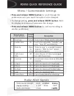
The speed codes and their meanings
Read over the following programming codes listed in the Speed Code Table
below to become familiar with the two-letter groups (modes) you want to set in
the sign using the push button. Concentrate on the “Normal Mode” (NM) and
“Violator Alerts”
(VA) modes only, for now.
Notice that they are grouped so that for
example, when
“VA” is selected, you can set the “Minimum Speed”, Flash (speed), Blank (speed),
etc. As the last numbers are entered, the display is ready and goes blank.
Adaptive Micro Systems LLC | 7840 North 86th Street | Milwaukee, WI 53224
Phone (800) 558-7022 | AdaptiveDisplays.com


