background image

EVO S


, Installation, Commisioning and Servicing Instructions  

41

EN

4.7.  Electrical connection

WARNING:

Ensure  that  the  general  electrical  power  supply  has  been  cut  off 

before starting any repair work

.

CAUTION:

It is mandatory to connect this boiler correctly to earth and to comply 

with standard for low-voltage electrical installations.

Provide a two-pole circuit breaker upstream of the boiler (distance 

between contacts: 3.5 mm minimum).

Fitting the electrical installation with a 30 mA differential protective 

device is strongly advised.

Please refer to the installation and user manuals of the NAVISTEM B3100 

boiler  controller  for  more  information  about  the  electrical  connections  on 

the control panel (characteristics of the electric power supply, cable cross-

sections and connections to the terminals).

4.7.1.  Control panel

IMPORTANT:

The front plastic panel must be replaced before starting up the boiler.  

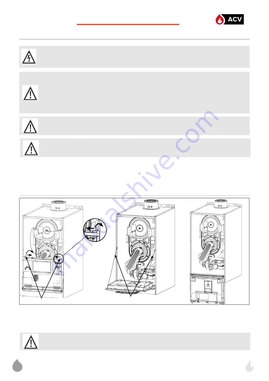
To  access  the  control  panel,  remove  the  front  of  the  boiler  see  chapter  4.2.

Push the latches forward and slide them inwards to unlock and tilt the control box.

It is possible to completely tilt the control box by removing the 

lanyards

, in 

Figure 17 - Access to NAVISTEM B3100 

Latches

00U07444570-A

Lanyards

CAUTION :

 Do not place anything on the control panel.

order to facilitate access to the interior of the boiler.

ATTENTION :

Compulsory use of the connector supplied with the product.  

Summary of Contents for EVO S 100

Page 1: ...MAINTENANCE MAINTENANCE INSTRUCTIONS INSTRUCTIONS 00U07428690 A_01 02 2023 EN For professional To be retained by the user for future reference Gas condensing BOILER with modulating burner for natural gas and and propane gas 40 60 70 80 100 120 150 kW ...

Page 2: ......

Page 3: ...pressures 12 3 TECHNICAL SPECIFICATIONS 14 3 1 Dimensions 14 3 2 Boiler components 16 3 3 Combustion at 15 C and 1013 mbar 19 3 4 Operating conditions 21 3 5 Electrical connection 21 4 INSTALLATION 22 4 1 Installing the boiler 22 4 2 Removing installing the front panel 24 4 3 Flue connection 24 4 4 Gas connection 34 4 5 Changing gas G20 to G31 for only 40 to 120 kW boilers 35 4 6 Hydraulic connect...

Page 4: ...ONFIGURATIONS 52 9 1 Symbols used in the diagrams 52 9 2 List of diagrams 52 10 SPARE PARTS LIST 106 11 CUSTOMER REGULATION PARAMETERS TABLE 116 12 OPTION KITS 132 12 1 Boiler mounted kits 133 12 2 External kits 140 13 APPENDIX A 147 14 INSTALLATION COMMISSIONING SERVICE RECORD LOG BOOK 148 ...

Page 5: ...fication of personnel for installation adjustment use and maintenance The operations to install adjust and maintain the boiler must be carried out by qualified and approved professionals in accordance with current local and national regulations UK require Gas Safe Installer IE require Registered Gas Installer RGII These operations requires intervention under voltage with the casing doors located o...

Page 6: ...ent ETCI rules for electrical installation The Boiler boilers have been tested and certified to BS EN 15502 1 BS EN 15502 2 BS EN 15502 2 1 BS EN 60335 1 BS EN 60335 2 102 BS EN 55014 1 and BS EN 55014 2 for use with Natural Gas Propane Detailed recommendations are contained in the following Codes of Practice BSEN 60529 IPX4D using test method Figure 4 Test device to verify protection against spra...

Page 7: ... gas appliances in industrial and commercial premises ICOM Water treatment and conditioning of commercial heating systems guide Where reference is made throughout these instructions I S 813 2002 Domestic Gas Installations reference should also be made to I S 820 2000 Non Domestic Gas Installations as applicable WARNING If you smell gas Do not use any naked flames smoke or activate any contacts or ...

Page 8: ... water capacity of the heating system Also the hardness of the make up water must be controlled Make up water Adding a large amount of untreated water always contributes a significant amount of scaling To monitor this and to detect problems a system water meter must be installed Failure to comply with these guidelines such that the fill water plus the make up water is more than three times the wat...

Page 9: ...sion vessel that allows direct passage Internal pressure with the unit of more than 1 bar cold Remove leaky permeable components that are letting out more gas than as if they were sealed If the guidelines above are followed the unit s system water has the proper characteristics to last a long time 8 2 pH 9 5 with a water concentration of 0 1 mg l If there is a chance that oxygen could enter the un...

Page 10: ...ed to use a form of hydraulic separation to protect the internal boiler components and extend the service life 1 5 6 Setting up a filtration system A filtration system on the back of the boiler is recommended in order to remove suspended particles from the unit filter sediment trap etc 1 6 Air quality For boilers to operate correctly the combustion air coming from outside must be free of dust Sign...

Page 11: ...fuels as amended by The Ecodesign for Energy Related Products and Energy Information Amendment EU Exit Regulations 2019 and is manufactured in accordance with the UK designated standards 2 2 Regulatory installation conditions for other countries See earlier reference to Gas Safe etc The appliance must be installed and maintained by a qualified professional in accordance with the regulations and cu...

Page 12: ...sures provided below must be taken at the input to the gas valve Natural gas H G20 Propane gas G31 Nominal pressure mbar 20 37 Minimum pressure mbar 17 25 Maximum pressure mbar 25 45 EVO S Installation Commisioning and Servicing Instructions EN 12 ...

Page 13: ... EVO S Installation Commisioning and Servicing Instructions 13 EN ...

Page 14: ...EVO S Installation Commisioning and Servicing Instructions EN 14 Figure 1 Dimensional characteristics 3 TECHNICAL SPECIFICATIONS 3 1 Dimensions ...

Page 15: ...outlet to side casing 66 5 65 5 I Center of return connection from casing side mm 73 5 74 5 J Centers between flow and return connections mm 190 K Centers between gas inlet and return connection mm 95 L Center of flue from side mm 240 M Center of flue from rear mm 146 5 123 N Flue connection socket height mm 83 Ø O Return connection G 1 1 4 Ø P Gas inlet connection G 1 Ø Q Flow connection G 1 1 4 ...

Page 16: ...re switch 2 Température sensor 3 Ignition transformer 4 Ionization and ignition electrode 5 Gas valve 6 Fan 7 Condensate siphon supplied unmounted 8 Water return temperature sensor 9 Bleed valve 10 Water outlet temperature sensor 11 Water pressure sensor 12 Water flow meter 13 EMC filter on 55 kW Note in order to facilitate viewing the side covers have been removed but these cannot be removed ...

Page 17: ...Ignition transformer 4 Ignition electrode 5 gas valve 6 Fan 7 Condensate siphon supplied unmounted 8 EMC filter 9 Water return temperature sensor 10 Trap 11 Water outlet temperature sensor 12 Ionization electrode 13 Pressure sensor 14 Flowmeter view without NAVISTEM B3100 unit Note in order to facilitate viewing the side covers have been removed but these cannot be removed ...

Page 18: ...5 Gas valve 6 Fan 7 Condensate siphon supplied unmounted 8 EMC filter 9 Water return temperature sensor 10 Bleed valve 11 Water outlet temperature sensor 12 Ionization electrode 13 Water pressure sensor 14 Water flow meter Figure 4 Boiler components for 150 model Note in order to facilitate viewing the side covers have been removed but these cannot be removed ...

Page 19: ... 8 7 4 8 5 10 2 12 7 15 3 Value range of CO2 at Qmin at Qmax min max 9 6 10 8 8 9 2 8 9 9 3 min max 8 8 9 2 Exhaust outlet interior diameter mm 80 80 80 100 100 100 100 Exhaust mass flow rate 80 60 C Qn Qmin g s 18 6 25 6 32 5 37 2 44 7 55 8 67 5 4 0 7 7 9 3 9 4 9 4 12 3 14 2 Exhaust mass flow rate 50 30 C Qn Qmin g s 16 8 23 1 29 3 33 6 40 3 50 3 60 8 3 6 6 9 8 4 8 5 8 5 11 1 12 8 Exhaust tempera...

Page 20: ... 10 2 at Qmax min max 10 3 10 7 9 8 10 2 Exhaust outlet interior diameter mm 80 80 80 100 100 100 Exhaust mass flow rate 80 60 C Qn Qall Qmin g s 17 8 24 5 31 2 35 7 42 8 53 5 3 6 4 9 6 2 8 6 8 6 10 7 Exhaust mass flow rate 50 30 C Qn Qall Qmin g s 18 9 25 9 32 9 37 7 45 2 57 1 3 8 5 2 6 6 9 0 9 0 11 4 Exhaust temperature 80 60 C Qn Qall Qmin C 76 76 74 67 73 74 62 62 62 56 56 58 Exhaust temperatu...

Page 21: ...ximum safe temperature C Max service pressure hPa bar Min cold pressure hPa bar Nominal water flow rate Pnom 20 m3 h Minimum water flow rate m3 h Water content L Weight without water kg Protection level Maximum installation altitude m MODELS in kW 40 60 70 80 100 120 150 5 45 C between 5 and 95 85 0 8 0 92 0 110 0 4000 4 6000 6 1000 1 1 72 2 36 3 00 4 16 4 30 5 16 6 23 0 57 1 15 2 30 3 00 3 44 3 4...

Page 22: ...y valve A siphon and a flexible hose for evacuating condensates An information plate for the 40 to 120 kW models switching to propane gas A gas adapter for the 70 to 120 kW models switching to propane gas 4 1 Installing the boiler IMPORTANT The boiler must not bear the weight of the accessories and connections hydraulics gas exhaust system etc WARNING The use of the fixing hooks supplied with the ...

Page 23: ...nance operations on the boilers The minimum values in mm are indicated in the diagram opposite and the following table These values cannot be substituted for the specific regulatory requirements B23 B23P C13 C33 40 to 70 80 to 150 40 to 70 80 to 150 40 to 70 80 to 150 ø80 ø100 ø130 ø100 ø130 ø150 ø80 125 ø100 150 ø80 125 ø100 150 A mm 393 450 530 289 416 426 290 325 145 145 The minimum dimension o...

Page 24: ...y where the boiler will be installed i e Theexhaustevacuationductsmustbemadeofamaterialthatisresistant to the condensates that can form during the boiler s operation and their correct fit must be checked These materials must also be capable of supporting flue gas temperatures up to 120 C Do not use non compliant modified or broken ducts One exhaust temperature sensor guarantees the protection of t...

Page 25: ...kW and over Detail reference should be made to BS 6644 and IGEM UP 10 for inputs between 70kW and 1 8MW net In IE refer to the current edition of I S 820 The following notes are for general guidance only If ventilation is to be provided by means of permanent high and low vents communicating direct with outside air then reference can be made to the sizes below For other ventilation options refer to...

Page 26: ... code 041050 is mandatory to connect the boiler to a B23 chimney duct This kit is suitable for Ø 150 external ducts IMPORTANT Under no circumstances is use of these mandatory accessories a substitute for checking the dimensioning of the chimney ducts given a combustion gas pressure at the boiler outlet equal to 0 Pa EVO S boilers are high performance boilers with very low exhaust temperatures cons...

Page 27: ...RTANT The use of the Chimney Adaptor accessory is mandatory to connect a EVO S boiler to a B23P chimney duct The table below shows the accessories available for each boiler type IMPORTANT Check that the boiler installation premises have high and low ventilation that it conforms to current regulations and that it is not obstructed The A dimension indicates the height of the chimney adapter when ful...

Page 28: ...nsion 195 mm min The Ø 100 chimney adapter have an outlet that cannot be cut A purge tee is not necessary because condensate recovery is incorporated in the boiler To do this use a minimum slope of 3 towards the boiler in the horizontal parts To ease fitting coat the joints with water IMPORTANT If several boilers are connected to the same flue check the following by calculation One boiler at Qmin ...

Page 29: ...be taken to support the inner duct when cutting the flue When assembling only use water as a lubricant Note Horizontal flue runs must be angled down between1 5 3 towards the water heater to allow the condensate to drain For this reason it is recommended that a support bracket is used for every 1m of extension pipe See below for flue assembly examples Cut the white terminal tube to the correct leng...

Page 30: ...ould be taken in the case of large multiple boiler installations and complying with the requirements of the Clean Air Act The information below is extracted from BS 5440 Pt 1 and is for boilers with heat inputs not exceeding 70kW nett and the latest Building Regulation Part J Detailed reference should still be made to these standards In IE refer to I S 813 2002 Table 1 Flue Terminal Position 1 In ...

Page 31: ...Horizontal flue positions Refer to table 1 4 3 5 2 VERTICAL FLUE POSITIONS Refer to table 1 HEAT INPUTS IN EXCESS OF 70kW NETT For boiler installations with total heat inputs in excess of 70kW nett reference should be made to BS6644 and IGEM UP 10 In IE refer to I S 820 2000 ...

Page 32: ...onnected to a vertical concentric terminal WARNING The use of the Horizontal suction pipe accessory is mandatory to connect the boiler to a C13 concentric suction pipe The use of the Vertical black suction pipe or Vertical ochre suction pipe accessory is mandatory to connect the boiler to a C33 concentric suction pipe Approved conduits are M G Skyline conduits and terminals may also be used Figure...

Page 33: ...The terminal location must comply with the rules in 4 3 3 Use a minimum slope of 3 towards the boiler For type C13 drill a 150mm hole in the wall for the 80 125 terminal and a 180 diameter hole for the 100 150 terminal Seal the air vent terminal into the wall with polyurethane foam to allow for removal if necessary To ease fitting coat the joints with water only EVO S 40 60 70 80 100 120 150 Sucti...

Page 34: ...r 125µm but this is not able to retain all the impurities contained in the gas and in the mains pipes To avoid any malfunction of the gas valve we advise the fitting of a suitable filter to the boiler gas supply 50µm If the gas valve pressure tap is used ensure that it is closed to avoid any leakage while running Before feeding gas to the installation ensure that the different connections are corr...

Page 35: ...d for the gas supply pressures at the valve inlet measured on the pressure meter before the gas valve and with the burner working in the following tables CAUTION Since the combustion is adjusted with the door open check that the combustion is clean after installing the front door CAUTION The setting mechanism must be sealed once the operation is complete All damaged seals must be replaced 4 5 1 in...

Page 36: ... Adjust the pre ventilation speed 9504 ignition speed 9512 minimum speed 9524 and maximum speed 9529 settings Models Gas 9504 9512 9524 9529 40 G20 4090 2430 2430 8740 G31 4090 3910 2350 8340 60 G20 4220 3280 2500 9500 G31 4220 3610 2400 9100 70 G20 4930 3160 2540 9500 G31 4930 3260 2400 9000 80 G20 3100 1930 1930 5500 G31 3100 1870 1870 5500 100 G20 3100 1930 1930 6450 G31 3100 1870 1870 6450 120...

Page 37: ...w screw Throttle R1 of the valve in order to obtain the CO2 values in the table below Change to minimum power Qmin and check that the CO2 value is within the range in the table below If necessary use the setting adjustment screw Offset R2 If the setting is adjusted at minimum power go back to maximum power Qmax and recheck the CO2 value Repeat the operation until both values comply with the table ...

Page 38: ...hrottle 10 3 10 7 10 8 11 2 70 G20 Throttle open 2 5 turns on closing Throttle closed 5 turns at maximum opening 8 8 9 2 9 6 10 G31 0 5 turns closed on throttle 10 3 10 7 10 8 11 2 80 G20 Throttle open 2 5 turns on closing unscrew 8 8 9 2 8 8 9 2 G31 0 5 closing turns on throttle screw 0 5 closing turns on offset screw in 9 8 10 2 10 2 10 6 100 G20 Throttle open 2 5 turns on closing unscrew 8 8 9 ...

Page 39: ... never exceed the flow rates specified in paragraph 3 4 3 4 Figure 15 Head losses The boilers are equipped with the following elements a manual drain pipework a flow sensor It is imperative to fit the boiler and its installation with the following components isolating valves on the flow and return pipeworks an expansion tank an effective drain mechanism a filling mechanism to be installed on the r...

Page 40: ...st freezing draining may be a solution After filling with water Check the water pressure on the pressure gauge not included This must be a maximum of 4 bar for 40 to 70 kw models or a maximum of 6 bar for 80 to 150 kW models when hot and a minimum of 1 bar when cold Check that the boiler and its installation are completely free of air check the boiler levelling with a spirit level Condensate remov...

Page 41: ...e NAVISTEM B3100 boiler controller for more information about the electrical connections on the control panel characteristics of the electric power supply cable cross sections and connections to the terminals 4 7 1 Control panel IMPORTANT The front plastic panel must be replaced before starting up the boiler To access the control panel remove the front of the boiler see chapter 4 2 Push the latche...

Page 42: ...act input Modulating pump Figure 18 Packing glands Cable Terminal strips Copper conductor cross section Power supply Power supply 3 x 1 5 mm Power QX1 QX2 QX3 3 x 1 mm Signals BX2 BX3 B3 B9 H1 H5 UX2 UX3 ambient temperature sensors 2 x 0 5 mm 4 7 4 Connections to terminals To connect the NAVISTEM B3100 boiler controller please refer to the installation and user manual Cable passage for signal conn...

Page 43: ...t for heat is in progress on the boiler If the circulation pump does not have a remote control Directly wire the power supply of the circulation pump 230 VAC 1A max to the terminal QX3 contacts L3 N and on the NAVISTEM B3100 panel If the circulation pump has electronic control or is high efficiency or consumes more than 1A the power supply must be via a contactor If the circulation pump is equippe...

Page 44: ...EVO S Installation Commisioning and Servicing Instructions EN 44 Figure 19 Wiring diagram ...

Page 45: ...EVO S Installation Commisioning and Servicing Instructions 45 EN ...

Page 46: ...ilers are subjected to a factory test using group H type G20 natural gas during which all the settings are done If the appliance is to be used on Group P gas G31 the boiler must be modified and adjusted to operate correctly For first use perform the following operations 1 Switch on the main circuit breaker 2 Create a request for heat via the comfort mode using the customer interface see the chapte...

Page 47: ...supply Check that the gas pipe diameter is correctly sized It is necessary to stop all the boilers together abruptly using the boiler room main circuit breaker to check that the gas pressure regulator safety device is not triggered If this is triggered the gas pipe is undersized After this operation reengage the circuit breaker The boilers must start automatically if not consult the supplier of th...

Page 48: ...ctrode gap width and the ionising electrode If necessary replace the electrodes Condensate removal siphon ANNUAL Clean the removal siphon and check that the condensate flows correctly Ensure the siphon is topped up with water after replacing Check the gas valve and the differential air pressure switch Check the connection of the pressure transfer pipe ANNUAL Carry out a combustion check 7 1 Draini...

Page 49: ... in the combustion chamber brush the tubes of the exchanger with a non metallic brush Chemical cleaning of the combustion chamber with an acid or alkaline product is forbidden Vacuum clean the deposits If the refractory insulation at the bottom of the combustion chamber and of the burner support is damaged then it must be replaced If the level of condensates in the combustion chamber has risen due...

Page 50: ... six nuts on 80 to 150 kW models Maximum tightening torque 5 Nm Connect the gas supply Check that the gas circuit is sealed with a foaming product Install the control panel Switch on the electric power supply Start the boiler check that the burner door is properly sealed and check the combustion The rate of CO2 must comply with the values in the table in paragraph 4 5 Install the front panel and c...

Page 51: ...disposal of the product and the component parts the services of an accredited waste disposal company should be used b For more information on waste disposal management contact the Local Authority responsible for waste management or the point of sales where the product was purchased EVO S Installation Commisioning and Servicing Instructions 51 EN ...

Page 52: ...ture sensor 9 2 List of diagrams BOILER ONLY 53 Control from and existing BMS 53 EVO S 1 Control 1 mixed circuit and production of DWH 58 EVO S 2 2 regulated circuits 1 direct circuit with low limit and production of DWH 63 EVO S 3 4 regulated circuits and DHW production 69 EVO S 4 1 non regulated circuit with sliding flow 77 EVO S 20 CASCADED BOILERS 81 DHW production with tank with coil 81 EVO S...

Page 53: ...gram EVO S 1 page 1 5 A HYDRAULIC DIAGRAM Figure 24 VFO1 diagram B OPTIONAL ACCESSORIES Quantity Appliance reference Communication kit for LPB bus 1 OCI 345 Communication kit for Modbus bus 1 OCI 351 EXISTING BMS Modbus bus to OCI 351 or LPB bus to OCI 345 or 0 10V signal temperature to B3100 OCI 351 or OCI 345 ...

Page 54: ...CRIPTION The existing regulation system controls the installation s heating circuit It sends the outlet temperature set point to the boiler either over the LPB bus through the OCI 345 interface SIEMENS protocol either by a 0 10 V signal sent directly to the NAVISTEM B3100 or over the Modbus bus through the OCI 351 interface When controlled by the external regulator the boiler operates according to...

Page 55: ...0V LPB Power supply primary Fault report 230Vac Boiler pump supply For the installation of a pump from your supply see page 119 at the end of the document Secondary bottle sensor B10 Boiler pump control Variant option 0 10V Control by 0 10V signal LPB bus control Variant LPB option Variant Modbus option Modbus bus control Diagram EVO S 1 page 3 5 ...

Page 56: ...utput sensor For a request via 0 10V input Configuration menu Configure the H1 input H1 input function 5950 10V consumption circ request H1 function 2 value 5956 1000 for equivalence 10 V 100 C Save the sensors so that they are taken into account by the system Save sensor BX3 6200 Yes switches back to no automatically OK OK Short press Press for 3 seconds End user Start up Specialist OEM Warning t...

Page 57: ...dress 6600 1 Segment address 6601 0 For your PLC to be the timestamp master Clock operation 5955 Slave with adjustment For a request via Modbus Setup menu Configure input H1 Function input H1 5950 Consumer circuit request 1 Contact action direction 5951 Work Modbus menu In the boiler s Modbus elements set the Slave address 6651 As it is set on your PLC Baud rate 6652 As it is set on your PLC Parit...

Page 58: ... Diagram EVO S 2 page 1 5 A HYDRAULIC DIAGRAM Figure 25 EVO S 2 diagram B OPTIONAL ACCESSORIES Quantity Appliance reference Outdoor sensor kit 1 QAC 34 DHW sensor kit 1 QAZ 36 Boiler pump supplied by the customer all or nothing control Extension module kit delivered with a network sensor QAD 36 1 AGU 2 550 DHW DHW LOOP DCW ...

Page 59: ...he AGU 2 550 interface built into the boiler is used to control the two three way regulating valves of the heating network The boiler operates in variable flow temperature according to the outdoor temperature measured by the exterior sensor QAC 34 without a low temperature limit The production of domestic hot water is controlled by the NAVISTEM B3100 using the QAZ 36 sensor in the tank Diagram EVO...

Page 60: ... Fault report 230Vac DHW pump Q3 230Vac Boiler pump supply Power supply AGU 2 550 Module 1 U BX22 M BX21 M H2 Regulated circuit output sensor B12 QX21 N QX22 N QX23 N L Mixing valve Heating circuit n 2 Y5 Y6 Heating circuit No 2 circulator Q6 AGU 2 550 No 1 on Power supply terminals 17 to 18 1 0 Heating regime toggle switch OR Temporary switch per timer relay ...

Page 61: ...n specialist mode Line No Value Time and date menu Set the time Hour minute 1 HH MM Set the date Day month 2 DD MM Set the year Year 3 YYYY SIGNALS CONNECTION Diagram EVO S 2 page 4 5 GND IN GND IN GND IN GND IN GND PWM GND 10V Secondary bottle sensor B10 External sensor B9 DHW sensor B3 Boiler pump supply OK OK Short press Press for 3 seconds End user Start up Specialist OEM ...

Page 62: ...ion 6046 Switching of heating circuit operation1 Save the sensors so that they are taken into account by the system Save sensor 6200 Yes switches back to no automatically Heating circuit 1 menu Adjust the comfort setting Comfort setting temperature 710 C Adjust the heating curve slope Curve slope 720 1020 1320 Switching to comfort mode with H2 contact Regime switching 900 Comfort Switch the heatin...

Page 63: ...on of DWH Diagram EVO S 3 page 1 6 A HYDRAULIC DIAGRAM Figure 26 EVO S 3 diagram DHW DHW LOOP DCW B OPTIONAL ACCESSORIES Quantity Appliance reference DHW sensor kit 1 QAZ 36 Outdoor sensor kit 1 QAC 34 Extension module kit delivered with a network sensor QAD 36 2 AGU 2 550 or Opentherm room sensor respecting the V4 0 Opentherm specification 1 ...

Page 64: ... boiler operates in variable flow temperature according to the outdoor temperature measured by the exterior sensor QAC 34 without a low temperature limit The production of domestic hot water is controlled by the NAVISTEM B3100 using the QAZ 36 sensor in the tank Diagram EVO S 3 page 2 6 C RECOMMENDED HYDRAULIC ACCESSORIES We offer a wide range of hydraulic accessories including support frame and h...

Page 65: ...BX21 M H2 Regulated circuit output sensor B14 QX21 N QX22 N QX23 N L Mixing valve heating circuit n 3 Y11 Y12 Heating circuit No 3 circulator Q20 AGU 2 550 No 2 on E CUSTOMER S ELECTRICAL CONNECTION POWER CONNECTION Main power supply Fault report 230Vac Direct circuit pump Q2 230Vac Boiler pump supply Power supply AGU 2 550 GND PWM H5 L N L N VF 40 120 145 6 2 3 4 5 1 7 AGU 2 550 6 2 3 4 5 1 7 AGU...

Page 66: ...Servicing Instructions EN 66 Diagram EVO S 3 page 4 6 SIGNALS CONNECTION GND IN GND IN GND IN GND IN GND PWM GND 10V Secondary bottle sensor B10 External sensor B9 DHW sensor B3 Boiler pump supply Room thermostat Opentherm bus CC3 GND OT ...

Page 67: ...p heating circuit 2 Heating circuit 2 5715 Start Start up heating circuit 3 Heating circuit 3 5721 Start Configure the alarm output Relay output QX1 5890 Alarm circuit K10 Configure the DHW tank pump output Relay output QX2 5891 DHW pump Q3 Configure the direct circuit pump Q2 Relay output QX3 5892 Pump CC1 Q2 Configure the extension modules Extension module function 1 6020 Heating circuit 2 Exten...

Page 68: ...s internal heating circuit is deactivated but the settings devices can still be controlled This means that all the internal functions of the Navistem B3100 related to heat request calculations are no longer active heating curve ambient influence ambience controller daily heating limiter summer switching time programming operating mode button accelerated temperature lowering accelerated heating fro...

Page 69: ...e DHW sensor kit 1 QAZ 36 Outdoor sensor kit 1 QAC 34 Extension module kit delivered with a network sensor QAD 36 2 AGU 2 550 Cascade regulator kit 1 RVS 63 Communication kit 1 OCI 345 DHW DHW LOOP DCW C RECOMMENDED HYDRAULIC ACCESSORIES We offer a wide range of hydraulic accessories including support frame and header kits and hydraulic separation options Please refer to specific ACV literature fo...

Page 70: ...e used to control the two three way regulating valves of the heating networks The other 2 will be controlled by the RVS63 integrated in an external unit The boiler operates in variable flow temperature according to the outdoor temperature measured by the exterior sensor QAC 34 without a low temperature limit The production of domestic hot water is controlled by the NAVISTEM B3100 using the QAZ 35 ...

Page 71: ...ing valve Heating circuit n 2 Y5 Y6 Heating circuit No 2 circulator Q6 AGU 2 550 No 1 on Module 2 U BX22 M BX21 M H2 Regulated circuit output sensor B14 QX21 N QX22 N QX23 N L Mixing valve heating circuit n 3 Y11 Y12 Heating circuit No 3 circulator Q20 AGU 2 550 No 2 on Main power supply Fault report 230Vac Boiler pump supply Power supply AGU 2 550 DHW pump Q3 230Vac Power supply terminals 17 to 1...

Page 72: ...ing and Servicing Instructions EN 72 EVO S SIGNALS CONNECTION Diagram EVO S 4 page 4 8 GND IN GND IN GND IN GND IN GND PWM GND 10V Secondary bottle sensor B10 External sensor B9 DHW sensor B3 Boiler pump supply LPB RVS 63 bus link ...

Page 73: ...4 mixer valve Y5 Y6 Heating circuit No 4 circulator Q6 Heating circuit No 3 mixer valve Y1 Y2 Heating circuit No 3 circulator Q2 230 VAC 50 Hz power supply Varino bus connection F SPECIFIC START UP PROCEDURE Correctly install and connect the electrical connections Make the settings below in specialist mode On the boiler Navistem B3100 Line No Value Time and date menu Set the time Hour minute 1 HH ...

Page 74: ...y are taken into account by the system Save sensor 6200 Yes switches back to no automatically LPB network menu Configure the boiler so that the secondary sensor requests that the boiler flow setpoint is increased if the primary secondary flows are not balanced Cascade master 6630 Permanent Configure the cascade Address of the interface on the bus Appliance address 6600 1 Segment number Segment add...

Page 75: ...s 6600 1 Segment number Segment address 6601 0 Adjust the clock rate Clock operation 6640 Slave without adjustment Heating circuit menu 1 2 3 Adjust the comfort setting Comfort setpoint temperature 710 1010 1310 C Adjust the curve slope Curve slope 720 1020 1320 Adapt the setpoint Summer winter heating limit 730 1030 1330 22 C Switching the function off Daily heating limit 732 1032 1332 C Adapt th...

Page 76: ...omfort Domestic hot water menu Adjust the DHW setpoint Comfort setting 1610 C Activate the DHW mode Refer to the ELECTRICAL VALIDATION chapter for the regulator input output tests Refer to the OPTIMISATION chapter for configuring the time slots for the heating and DHW circuits as well as for programming the anti legionella cycles ...

Page 77: ... B3100 with or without a low temperature limit and with a weekly programme The heating pump must be able to operate at a constant speed to ensure the minimum flow rate that is required by the generator If the installation is equipped with thermostatic taps on the emitters the bypass between the outward and return lines of the network is essential It is equipped with a differential valve that allow...

Page 78: ...EVO S Installation Commisioning and Servicing Instructions EN 78 B NECESSARY REGULATION ACCESSORY Quantity Appliance reference Outdoor sensor kit 1 QAC 34 Diagrams EVO S 20 page 2 4 ...

Page 79: ...Servicing Instructions 79 EN Diagrams EVO S 20 page 3 4 C CUSTOMER S ELECTRICAL CONNECTION POWER CONNECTION Main power supply Fault report 230Vac Direct circuit pump Q2 230Vac External sensor B9 GND IN GND IN GND IN GND IN GND PWM GND 10V ...

Page 80: ...irect circuit pump Q2 Relay output QX3 5892 Pump CC1 Q2 Save the sensors so that they are taken into account by the system Save sensor 6200 Yes switches back to no automatically Heating circuit 1 menu Adjust the comfort setting Comfort setting temperature 710 C Adjust the curve slope Curve slope 720 Adjust the min flow temperature for heating circuit 1 Minimum flow temperature setpoint 740 60 C ad...

Page 81: ...rates at the flow temperature required to produce the domestic hot water The heating pump must be able to operate at a constant speed to ensure the minimum flow rate that is required by the generator The domestic hot water production system has its own regulator A sensor QAZ 36 positioned inside the storage tank and connected to the generator informs the boiler of the need for domestic hot water D...

Page 82: ... Servicing Instructions EN 82 Diagram EVO S 24 page 2 3 D CUSTOMER S ELECTRICAL CONNECTION POWER CONNECTION Main power supply Fault report 230Vac Boiler pump Q1 DHW sensor B3 GND IN GND IN GND IN GND IN GND PWM GND 10V SIGNALS CONNECTION ...

Page 83: ...r pump Relay output QX2 5891 Boiler pump Q1 Configure the DHW tank pump output so that the system can activate DHW mode The Qx4 output cannot thus be used for any other functions Relay output QX4 5893 DHW pump Q3 Save the sensors so that they are taken into account by the system Save sensor 6200 Yes switches back to no automatically Domestic hot water menu Adjust the DHW setpoint Comfort setting 1...

Page 84: ...ommunication kit 2 3 OCI 345 Communication kit for Modbus bus for dialogue via Modbus bus 1 OCI 351 Network sensor kit 1 QAD 36 EXTERNAL BMS Modbus bus to OCI 351 or LPB bus to OCI 345 or 0 10V signal temperature to B3100 OCI 351 or OCI 345 C RECOMMENDED HYDRAULIC ACCESSORIES We offer a wide range of hydraulic accessories including support frame and header kits and hydraulic separation options Ple...

Page 85: ... that is the master of the cascade or over the LPB bus or Modbus to each NAVISTEM B3100 The cascade of boilers is controlled by the installation s regulation system according to the needs The setpoint sent reflects the heating temperature that the installation needs at this precise moment E CUSTOMER S ELECTRICAL CONNECTION Boiler 1 LPB 0 10V Secondary probe cascade cylinder B10 GND IN GND IN GND I...

Page 86: ... Instructions EN 86 Main power supply Fault report 230Vac Boiler pump supply Boiler pump supplied with the kit For the installation of a pump from your supply see page 119 at the end of the document Diagram EVO S 10 page 3 7 Boiler 2 and following ...

Page 87: ...N Boiler 2 and following Diagram EVO S 10 page 4 7 0 10V Secondary probe cascade cylinder B10 GND IN GND IN GND IN GND IN GND PWM GND 10V Order by Modbus bus Communication between boilers Pump control boiler Next boiler Communication between boilers Previous boiler ...

Page 88: ...1 function 2 value 5956 1000 for equivalence 10 V 100 C Save the sensors so that they are taken into account by the system Save sensor 6200 Yes switches back to no automatically Attention the boiler considers a heat request for a H1 voltage 0 2 V and a resulting setpoint 6 C The boiler no longer considers a heat request for a H1 voltage 0 2V or a resulting setpoint 4 C In this second case the boil...

Page 89: ...5 Master or Slave with adjustment if the PLC is the master clock If you want an alarm report on this module output K10 QX1 containing all the faults from all the modules Alarm relay system messages 6611 Yes For a request via Modbus Setup menu Configure input H1 Function input H1 5950 Consumer circuit request 1 Contact action direction 5951 Work Modbus menu In the boiler s Modbus elements set the S...

Page 90: ...ings in your PLC Appliance address 6600 1 Segment address 6601 0 For your PLC to be the timestamp master Clock operation 5955 Slave without adjustment Diagram EVO S 10 page 7 7 CAUTION Connect the bus between the boilers pay attention to the polarity Switch off then switch on the slave boiler s If the communication has been correctly established the clock is updated correctly ...

Page 91: ...er kits and hydraulic separation options Please refer to specific ACV literature for detailed information on these products D OPERATING DESCRIPTION The master NAVISTEM B3100 controls the cascade of boilers on the basis of the outlet temperature measured by the sensor QAD 36 Each NAVISTEM B3100 controls the charge pump of its own generator The boilers operate with a variable outlet temperature acco...

Page 92: ... Q3 230Vac Power supply AGU 2 550 Boiler pump supplied with the kit Module 1 U BX22 M BX21 M H2 Regulated circuit output sensor B1 QX21 N QX22 N QX23 N L Mixing valve heating circuit n 1 Y1 Y2 Heating circuit No 1 circulator Q2 AGU 2 550 No 1 on Module 2 U BX22 M BX21 M H2 Regulated circuit output sensor B12 QX21 N QX22 N QX23 N L Mixing valve Heating circuit n 2 Y5 Y6 Heating circuit No 3 circula...

Page 93: ...misioning and Servicing Instructions 93 EN Diagram EVO S 11 page 2 7 Boiler 2 and following GND IN GND IN GND IN GND IN GND PWM GND 10V Communication between boilers Next boiler Communication between boilers Previous boiler ...

Page 94: ...tput QX1 5890 Alarm circuit K10 Configure DHW pump Q3 Relay output QX3 5892 Valve DHW pump Q3 Configure the extension module 1 Extension module function 1 6020 Heating circuit 1 Configure the extension module 2 Extension module function 2 6022 Heating circuit 2 Save the sensors so that they are taken into account by the system Save sensor 6200 Yes switches back to no automatically LPB network menu...

Page 95: ... function 2 6022 Heating circuit 2 Save the sensors so that they are taken into account by the system Save sensor 6200 Yes switches back to no automatically Menu LPB network Configure as master of the cascade Number of the appliance Appliance address 6600 2 or following for other cascades Segment number Segment address 6601 0 Adjust the clock rate Clock operation 6640 Master If you want an alarm r...

Page 96: ...status H5 7865 Open closed 230Vac outputs test Alarm output Relay test 7700 Output QX1 Programmable output QX2 DHW pump Relay test 7700 Output QX2 Programmable output QX3 Q2 direct circuit pump Relay test 7700 Output QX3 Programmable output QX21 module 1 CC1 V3V opening Relay test 7700 Output QX21 Module 1 Programmable output QX21 module 2 CC2 V3V opening Relay test 7700 Output QX21 Module 2 Progr...

Page 97: ...00 00 h Adjust the timer programming for CC1 CC2 CC3 1st Phase OFF 502 522 542 06 00 h Adjust the timer programming for CC1 CC2 CC3 2nd Phase ON 503 523 543 22 00 h Adjust the timer programming for CC1 CC2 CC3 2nd Phase OFF 504 524 544 24 00 h OK OK OK OK OK OK Time and date User interface CC1 time program Short press 500 Mon Sun Preselection 1st phase ON 1st phase OFF 501 502 06 00 22 00 Put the ...

Page 98: ...on 641 651 661 Monday Sunday Adjust the timer programming for CC2 Preselection 642 652 662 days months Adjust the timer programming for CC3 Preselection 643 653 663 days months Line No Value Menu Heating circuit 1 2 Adjust the reduced mode setting Reduced setpoint T 712 1012 C ECO function for automatic summer winter switch see NAVISTEM B3100 manual Summer winter heating limit 730 1030 19 C Daily ...

Page 99: ...e more than one heating circuit activated on the boiler proceed as follows OPTIMISATION page 3 4 OK OK OK OK OK OK Time and date User interface CC1 time program Short press 500 Mon Sun Preselection 1st phase ON 1st phase OFF 501 502 06 00 22 00 Short press Heating circuit Selection OK Short press Short press Short press Short press Line No Value Configuration menu Activate the heating circuits fro...

Page 100: ...t water menu Activate anti legionella mode Anti legionella function 1640 stop periodic fixed day of the week Choice of repetition From daily to every 7 days 1641 periodic Periodical anti legionella function 1641 1 to 7 days Choice of day of the week if 1641 fixed weekday Legionella function day week 1642 Monday Sunday Anti legionella launch time Times of anti legionella operation 1644 00 00 Heatin...

Page 101: ...e 5020 16 C Adjustment on an ACV Rubis W3000 or Rubis EVO W3100 preparation unit without a savings and performance kit Parameters menu DHW production Main setpoint C1 C1 setpoint 62 C Summary of the rules for DHW set point adjustment on the EVO S Setpoint of consuming circuit 1 1859 setpoint C1 Rubis 5 C 67 C DHW setpoint 1610 setpoint C1 rubis 2 C 60 C Boiler setpoint temperature over value 5020 ...

Page 102: ... 5020 16 C Adjustment on an ACV Rubis W3000 or Rubis EVO W3100 preparation unit without a savings and performance kit Parameters menu DHW production Main setpoint C1 C1 setpoint 58 C Summary of the rules for DHW set point adjustment on the EVO S Setpoint of consuming circuit 1 1859 setpoint C1 Rubis 10 C 68 C DHW setpoint 1610 setpoint C1 rubis 2 C 58 C Boiler setpoint temperature over value 5020 ...

Page 103: ... of a supplied pump controlled by an On Off signal Connect the boiler directly to output Qx3 if consumption is 1A otherwise use a relay to interface If the pump has an On Off control switch it is best to control with a relay switch connected to output Qx3 Settings on the Navistem B3100 Line No Value Configuration menu Activate the output to control the boiler pump Relay output QX3 5892 Boiler pump...

Page 104: ...uarantee the temperature at the secondary it is advisable to place a sensor after the mixing bottle the kit reference and its implementation is described below Settings on the Navistem B3100 No line Value Setup Menu Configure the secondary flow sensor optional Sensor input BX2 5931 line flow sensor B10 Boiler Menu Set the minimum rotation speed of the pump Speed rot min pump 2322 Set the maximum r...

Page 105: ...and repeat these same steps to set the maximum flow command Step 1 Line No Value Menu Input output tests Define the control value in to control the boiler pump speed The 0 100 scale roughly corresponds to the 0 10V control scale Request via manual control Test output P1 7713 0 to 100 For example if the pump from the kit is used for a 70kw boiler the value to be entered here would be 35 Step 2 Line...

Page 106: ...EVO S Installation Commisioning and Servicing Instructions EN 106 Figure 32 EVO S casing 10 SPARE PARTS LIST 00U07446310 A I II 001 002 003 004 005 006 007 ...

Page 107: ...001 Front jacket 200316 200317 002 Complete user interface flap 78703 003 Blue front panel 200322 004 Power plug 200110 005 Wall fixing hook 200246 006 Concentric adaptor 200305 200306 007 Flue adaptater gasket D80 D100 interior 200307 200308 Front Jacket fasteners 200320 Front jacket complete fixing system 200321 ...

Page 108: ...EVO S Installation Commisioning and Servicing Instructions EN 108 Figure 33 Control panel 00U07446060 A II 101 102 103 104 105 106 108 107 109 110 105 111 ...

Page 109: ...interface with selector 78477 111 Complete control panel 200112 200113 200115 200116 200117 200119 200120 Display cover 200109 Complete electrical cabinet 76523 Customer power supply connector 76148 Customer Signal wiring 200144 Customer Power wiring 200146 Internal Signal wiring 200147 200149 Internal Power wiring 200148 200150 OCI 345 ribbon cable 200151 OCI 351 ribbon cable 200297 EMC filter ho...

Page 110: ...vicing Instructions EN 110 Figure 34 Body and burner for 70 kW models and lower 00U07446350 A III 201 202 203 204 205 206 207 208 209 210 211 213 212 214 215 216 217 218 219 220 230 231 221 222 223 224 225 211 229 228 227 226 225 225 225 225 ...

Page 111: ...lastic funnel M1 2 200247 215 Exchanger bottom refractory insulation 76470 216 Seal burner holder 200187 217 Burner holder refractory insulation 200196 218 Ignition electrode seal 200190 219 Ignition electrode seal 200188 220 Complete burner holder 200167 200168 200169 221 Flue gas temperature probe 76516 222 Body smoke seal 76512 223 Flow meter 76513 224 Pressure sensor and clip 200095 225 Hydrau...

Page 112: ...s EN 112 Figure 35 Body and burner for 80 to 120 kW models 00U07447310 A IV 301 302 303 304 305 306 307 308 309 310 311 312 313 314 315 316 317 318 319 320 321 322 323 324 325 326 327 328 329 330 332 333 334 335 336 337 338 339 340 331 307 307 307 307 341 339 ...

Page 113: ...n electrode seal 200206 323 Burner holder refractory insulation 76472 324 Complete burner holder 200170 200179 325 Door heat exchanger safety thermostat 76475 326 Gas outlet seal 72519 327 Flow meter 76513 328 Pressure sensor and clip 200095 329 Gas tube 200233 200234 330 G31 injector 200209 200210 G25 injector 200255 200259 331 Gas valve 200291 332 Gas valve outlet elbow flange 200212 333 Return ...

Page 114: ...s EN 114 Figure 36 Body and burner for 150 kW model 00U7444900 A V 401 402 403 404 406 407 408 409 410 411 412 413 414 415 416 417 418 419 420 421 422 423 424 425 426 427 428 430 434 435 436 437 438 439 440 441 405 411 411 411 411 429 431 432 433 409 441 406 ...

Page 115: ...eal 200191 422 Ignition electrode seal 200189 423 Burner ramp gasket 200201 424 Premix trunk 200200 425 Ionization Electrode seal 72506 426 Ionization electrode seal 200206 427 Burner holder refractory insulation 76472 428 Complete burner holder 200181 429 Rear heat exchanger safety thermostat 76475 430 Gas outlet seal 72519 431 Hydraulic collector with sensors 200092 432 Gas valve outlet elbow fl...

Page 116: ...ime S dd mm User interface 20 Language U English 22 Temporary M info 26 Operation locking M stop 27 Programming locking M stop 28 Direct adjustment M with validation 29 Units U C bar 42 Assignment appliance 1 M CC 1 44 Heating circuit 2 operation M common with heating circuit 1 46 Heating circuit 3 P operation M common with heating circuit 1 70 Software version M Timer programme 1 Heating circuit ...

Page 117: ...1st period stop time U 22 00 563 2nd period start time U 564 2nd period stop time U 565 3rd period start time U 566 3rd period stop time U 576 Default values U Frost protection Timer programme 5 600 Preselection U Mon Sun 601 1st period start time U 06 00 602 1st period stop time U 22 00 603 2nd period start time U 604 2nd period stop time U 605 3rd period start time U 606 3rd period stop time U 6...

Page 118: ...r value CC1 accelerated heating S 3 C 780 Quick reduction CC1 S stop 790 Max advance optimise switch on time CC1 S 00 00 791 Max advance optimise switch off time CC1 S 00 00 800 Start of increase Reduced setpoint TA CC1 S 5 C 801 End of increase reduced set point TA CC1 S 15 C 809 Uninterrupted pumps operation S no 820 Overheating protection Circuit to pump CC1 S on 830 Mixing valve setpoint over ...

Page 119: ... 1091 Max advance optimise switch off time CC2 S 00 00 1100 Start of increase Reduced ambient temperature setpoint Heating circuit 2 S 5 C 1101 End of increase reduced set point Heating circuit 2 S 15 C 1120 Overheating protection pump CC2 S on 1130 Mixing valve setpoint over value CC2 S 3 C 1132 Motor control mode heating circuit 2 S 3 points 1133 Servomotor differential heating circuit 2 S 2 C 1...

Page 120: ... CCP to pump S on 1430 Mixing valve setpoint over value CCP S 3 C 1432 Servomotor regulation type CCP S 3 points 1433 Servomotor differential CCP S 2 C 1434 Servomotor travel time CCP S 120 s 1435 Band P Xp CCP S 32 C 1436 Integration time Tn CCP S 120 s 1450 Screed drying function CCP M stop 1451 Manual setpoint for drying concrete screeds CCP M 25 C 1461 Over temperature reduction CC3 S always 1...

Page 121: ... 1959 Flow setpoint T M 70 C 1975 Excess heat absorption S 1 1978 With storage tank S no 1980 With prim regul primar pump S no Pool 2056 Boiler setpoint S 22 C Pre regulator supply pump 2110 Min start temperature limitation pre regulator S 8 C 2111 Max start temperature limitation pre regulator S 80 C 2130 Mixing valve setpoint over value Pre regulator S 7 C 2150 Pre regulator supply pump S after ...

Page 122: ...d S 40 60 70 80 100 120 150 8740 9500 9500 5500 7400 7400 6100 2450 Regulator timer S heating regime and DHW 2452 Regulator speed timer S 40 60 70 80 100 120 150 2350 2350 2400 2400 2400 2400 2000 2000 2000 2000 2000 2000 2000 2000 2454 Heating circuit activation differential S 3 C 2455 Min heating circuit disc different S 3 C 2456 Max heating circuit disc different S 6 C 2457 Heating circuit tran...

Page 123: ...turn setpoint S 8 C 3562 Cascade return limit influence on consumer circuit S on Solar 3810 Temperature difference Solar on S 8 C 3811 Temperature difference Solar off S 4 C 3812 DHW tank minimum charging temperature S 30 C 3813 Tank activation differential S 8 C 3814 Tank stop differential S 4 C 3815 Min storage tank loading temperature S 30 C 3818 Minimum pool loading temperature S 30 C 3822 Tan...

Page 124: ... B1 4796 Direction of operation return bypass S lowering of return T 4800 DHW partial load setpoint S 60 C 4810 Storage tank continuous load S stop 4811 Min T full load S 8 C 4813 Full load sensor S with B42 B41 Drinking water tank 5020 DHW flow setpoint over value S 10 C 5021 DHW refill over value S 8 C 5022 DHW loading regulation S complete charge 5030 DHW loading time limitation S 150 min 5040 ...

Page 125: ...peed S 40 5531 Instantaneous water heater max pump speed S 100 5550 Aqua booster S no General functions 5570 dT regul on dT 1 S 20 C 5571 dT regul off dT 1 S 10 C 5572 Regul min act time dT 1 S 0 C 5573 Sensor 1 regulator dT 1 S none 5574 Sensor 2 regulator dT 1 S none 5575 Min on time regdT1 S 0 s 5577 Pump valve kick start K21 S on 5580 dT regul on dT 2 S 20 C 5581 dT regul off dT 2 S 10 C 5582 ...

Page 126: ...t funct M none 6026 Module 2 EX21 input funct M none 6028 Module 3 EX21 input funct M none 6030 Relay output QX21 module 1 M none 6031 Relay output QX22 module 1 M none 6032 Relay output QX23 module 1 M none 6033 Relay output QX21 module 2 M none 6034 Relay output QX22 module 2 M none 6035 Relay output QX23 module 2 M none 6036 Relay output QX21 module 3 M none 6037 Relay output QX22 module 3 M no...

Page 127: ...tput function UX21 module 1 S none 6241 Logic signal output UX21 module 1 S standard 6242 Signal output UX21 module 1 S PWM 6243 Output function UX22 module 1 S none 6244 Logic signal output UX22 module 1 S standard 6245 Signal output UX22 module 1 S PWM 6246 Output function UX21 module 2 S none 6247 Logic signal output UX21 module 2 S standard 6248 Signal output UX21 module 2 S PWM 6249 Output fu...

Page 128: ...elay reset M no 6740 Output 1 T alarm S 120 min 6741 Output 2 T alarm S 120 min 6742 Output 3 T alarm S 120 min 6743 Boiler T alarm S 120 min 6745 DHW charging alarm S 8 h 6800 History 1 S 00 00 6805 Software diagnostic code 1 S 0 6810 History 2 S 00 00 6815 Software diagnostic code 2 S 0 6820 History 3 S 00 00 6825 Software diagnostic code 3 S 0 6830 History 4 S 00 00 6835 Software diagnostic cod...

Page 129: ...de 20 S 0 6999 Fault history reset S Maintenance 7040 Maintenance interval burner operating hours S 1500 h 7041 Burner operating hours since maintenance S 0 h 7042 Maintenance interval burner start ups S 9000 7043 Burner starts since last maintenance S 0 7044 Maintenance interval S 24 months 7045 Time since maintenance S 0 months 7050 Speed limit fan rotation For maintenance message S 0 7051 Signa...

Page 130: ...2 PWM value module 3 M Status Cascade diagnostic Generator diagnostic 8318 Max burnt gas temperature M 8378 Global heating energy S 8379 Global DHW energy S 8381 Heating gas energy S 8382 DHW gas energy S Consumer diagnostic 8701 Minimum outdoor temperature U 8702 Maximum outdoor temperature U 8703 Resulting outdoor temperature U 8742 Modem ambient temperature CC1 S 8772 Modem ambient temperature ...

Page 131: ...20 150 8740 9500 9500 5500 6450 7400 6100 9626 Power slope fan speed S 40 60 70 80 100 120 150 219 1 172 8 135 9 38 8 61 70 61 7 42 1 9627 Section Y fan power speed S 40 60 70 80 100 120 150 23 9 6 2 2 2 9 2 8 2 8 4 5 9650 Chimney drying S stop 9651 Chimney drying speed setpoint S 40 60 70 80 100 120 150 2350 2400 2400 1870 2000 2000 1650 9652 Chimney drying time S 10 min ...

Page 132: ...4 STRAP ON TEMP SENSOR 12 UIN 235784 MERLEY SEQUENCER ASSEMBLED 13 UIN 235785 MERLEY SEQUENCER KIT 14 UIN 235788 HEATING CIRCUIT CONTROL ASSEMBLED 15 UIN 235789 HEATING CIRCUIT CONTROL KIT Notes Only two locations are available within the boiler installer wiring area for items 1 to 4 which each take up one location when fitted The instructions for kits3 6 and 12 to 14 are provided with the kit all...

Page 133: ...ut the existing right hand side hole with a 3 mm drill 2 Put the supplied machine screw through the 3 mm hole from the rear and attach the nut loosely 3 Attach the left hand side this is identified by the two electrical connections brown and blue of the relay onto the machine screw and tighten 4 Align the relay level with the control housing and m rk the position of the right hand side fixing poin...

Page 134: ... circuit QX1 may be reconfigured and the VFC pump control kit mains lead may be connected to QX1 but this 230V relay output will need to be configured 12 1 1 4 Configuration for a Heating Circuit HC operation HC pump HC On Off demand Line No Parameter Settings 5710 Heating circuit 1 On Off 5715 Heating circuit 2 On Off 5721 Heating circuit 3 On Off Line No Parameter Settings 5890 QX1 Heat circuit ...

Page 135: ...tallation manual as required when carrying out the installation 12 1 2 1 Install the kit as follows On the AGU2 550A109 make sure that the dip switches are set as j this is the default factory setting Attach the AGU 2 550A109 into the support holes between the electrical connections Install the RAST5 plug into connection X1 Install the multicoloured cable into connection X50 ...

Page 136: ...ue wire N 2 Connect the opposite end of the cable into terminal 17 live and terminal 18 neutral as shown Contacts on X1 N 6 and QX21 7 230V can be used for the following Boiler flame on Boiler demand closed contact Contacts on N 4 and QX22 5 230V can be used for the following Fault errors closed contact E133 flame failure E110 temperature high limit E132 low gas pressure E132 flue or condensate bl...

Page 137: ...ent to full anticlockwise Mode UX42 jumper should be left set to position b it has no influence on the operation of channel 1 This is the default factory setting Attach the AGU 2 551A109 into a vacant clip in space into the support holes between the electrical connections only 2 clip in devices or one clip in and a VFC pump control relay may be fitted at any one time Externally mounted option kits...

Page 138: ...50 Make the following connection using the cable supplied between the Boiler PELV installer connections and the Clip in module X2 plug 12 1 4 3 Pump wiring Make the following connections between the AGU2 551 and the external pump 0 10V analogue input connections Boiler connector AGU2 551 X2 19 Pin 5 M 20 Pin 6 PI41 ...

Page 139: ...ess Bus between a boiler and another external LPB device boiler or External module Note For operation in a cascade each boiler in the cascade requires an LPB interface fitting One of the boilers must designated as a Cascade master 12 1 5 1 Location The location is fixed and is shown below insert photograph For cascade operation a 2 core cable is required to be run between the Boiler LPB terminals ...

Page 140: ...he two inner conductors and crimp on ferrules 8 Secure the cables DB Brown MB White 9 Plug the RAST5 connector back into the OCI345 note that the connector is polarised and so the screw heads face towards the control box 12 1 5 3 Wiring For cascade operation connect each LPB bus connection in daisy chain DB to DB MB to MB etc For an external module refer to the installation documentation provided ...

Page 141: ...equires 24mA so if more are required to be fitted and wired to the boiler then the 3 wire option must be used Note In an electrically noisy environment it is recommended that a screened cable be used The screen should only be connected to ground at one end 12 2 1 2 Fixing Follow the fixing instructions as detailed 12 2 1 3 Wiring At the QAA74 route and make the connections as shown in figure n avo...

Page 142: ... size 12 2 2 4 Fixing Follow the fixing instructions as detailed on the box 12 2 2 5 Wiring Cross sectional area Maximum length 0 25 mm2 20 m 0 5 mm2 40 m 1 0 mm2 80 m 1 5 mm2 120 m At the QAA74 route and make the connections as shown At the QAC34 route and make the connections as shown At the Boiler end make the connections GND 23 and B9 24 For an external module refer to the installation documen...

Page 143: ...2 wire connection requires 24mA Note In an electrically noisy environment it is recommended that a screened cable be used The screen should only be connected to ground at one end 12 2 3 2 Fixing Follow the fixing instructions as detailed on the box 12 2 3 3 Wiring At the QAA55 route and make the connections as shown avoid overlapping any of the individual wires during routing from the wall outlet ...

Page 144: ... cable length is required a 2 core cable is only required to be run between the Insertion Temperature Sensor and the associated Boiler or External module Use an appropriate electrical connection box securely mounted in which to make the connection between the sensor cable and the additional cable Note In an electrically noisy environment it is recommended that a screened cable be used The screen s...

Page 145: ...carrying out the installation 12 2 5 1 Application The Strap on Temperature Sensor may be used for several applications where a temperature measurement for system operation is required Common examples are a Cascade Common flow sensor B10 b DHW tank sensor B3 c DHW outlet flow sensor B38 d Heating circuit flow temperature sensor B1 B12 B14 Note It is recommended that a Strap on Sensor should not be...

Page 146: ...20 GND 21 BX2 22 GND 25 B3 B38 26 For an external module refer to the installation documentation provided with the specific option kit 12 2 5 7 Configuration Line No Parameter Settings 5931 Sensor input BX2 As required 5932 Sensor input BX3 As required DHW sensor B3 B38 5730 DHW sensor As required DHW sensor B3 Thermostat DHW outlet sensor B38 5131 Comparison temperature transfer As required DHW s...

Page 147: ...0 004 0 004 Other properties Heat loss Pstby kW 0 052 0 054 0 056 Nitrogen oxide emissions NOx PCS mg kWh 36 39 39 Annual energy consumption QHE kWh 1 2 2 Acoustic power LWA dB 50 59 60 Product data 400 kW Product reference Trade mark ACV Model 80 100 120 150 Nominal power Prated kW 78 0 94 0 117 0 142 0 Useful heat production At nominal power and in 80 C 60 C regime P4 kW 77 8 93 4 116 8 141 1 η4...

Page 148: ...mission this appliance to the manufacturer s instructions may invalidate the warranty This does not affect your statutory rights The use of this Log is to enable the safety features of this boiler to be proven a principle that is enshrined in health and safety law and endorsed by the Building Regulations Health Safety Executive as well as Gas Safe OFTEC and TRANSCO ...

Page 149: ...EVO S Installation Commisioning and Servicing Instructions 149 EN ...

Page 150: ...EVO S Installation Commisioning and Servicing Instructions EN 150 ...

Page 151: ...EVO S Installation Commisioning and Servicing Instructions 151 EN ...

Page 152: ...EVO S Installation Commisioning and Servicing Instructions EN 152 ...

Page 153: ...EVO S Installation Commisioning and Servicing Instructions 153 EN ...

Page 154: ...St David s Business Park Dalgety Bay KY11 9PF Fife United Kingdom Phone 44 0 1383 820100 Fax 44 0 1383 820180 uk sales acv com www acv com ACV adopts a policy of continuous improvement in the design and performance of its products Therefore the right is reserved to vary specifications without notice ...

Reviews: