A
Compact Condens : A1003043 - 664Y7200 • A
en
26
EN
FR
NL
ES
IT
DE
PL
RU
INSTALLATION
SYSTEM CONFIGURATIONS
The Compact Condens boilers can be setup in different types of systems, either high or low temperature,
or both, with or without Domestic Hot Water tank. They can also be configured in a Cascade system (using
an external controller like a 0-10V modulation signal or a control unit). Only the hydraulics and electronics
systems can be connected in a cascade, not the flue system.
It is up to the installer to determine the best solution for the results the user is expecting.
One basic configuration is shown in this manual (see next page), for any other configuration, please con-
tact your ACV representative.
BOILER LOAD SETTINGS
At the factory, the maximum load of the boiler was measured within 5% tolerance from the nominal load.
In the field the load can decrease due to more resistance in the boiler, the air inlet or the exhaust outlet
or due to a malfunction of the fan.
At maximum load, the system should be designed for a nominal ΔT of 15 K to 20 K.
When the ΔT is higher than 25 K, the boiler cannot run on maximum load anymore and will start to mod-
ulate because of an insufficient water flow through the boiler.
Flow and return temperatures can be read in the boiler information menu (through the DIAGNOSTICS
menu, refer to “User’s menu and parameter descriptions” on page 9 and “Installer’s menu and param-
eter descriptions” on page 12).
Valves, malfunctioning pumps, dirt, corrosion products from the system, dirty filters etc. can have nega-
tive impact on water flow through the boiler.
Before ignition the boiler control checks ΔP aps during pre-purge. During burner operation, this check
will be carried out. If the value is decreasing over the years, this could indicate e.g. malfunctioning of the
fan, polluted air inlet, polluted burner, polluted heat exchanger or polluted exhaust system.
Syphon pressure (P SPS) should be smaller than the maximum allowable flue resistance. If P SPS is too
high (> 8,3 mbar), the boiler will be stopped.
In this case the exhaust system is probably blocked. Refer to “Troubleshooting” on page 34 for more
information and to “Maintenance” on page 30.
GAS CONNECTION
Essential recommendations for safety
•
The gas connection must comply with all applicable local standards and
regulations, and the circuit will be equipped with a gas pressure regulator as
required.
•
The gas burners are factory preset for use with natural gas [equivalent to G20].
•
The CO
2
, gas flow rate, air flow rate and air/gas supply parameters are factory-
preset and may not be modified
in Belgium
, except for type I 2E(R)B boilers.
•
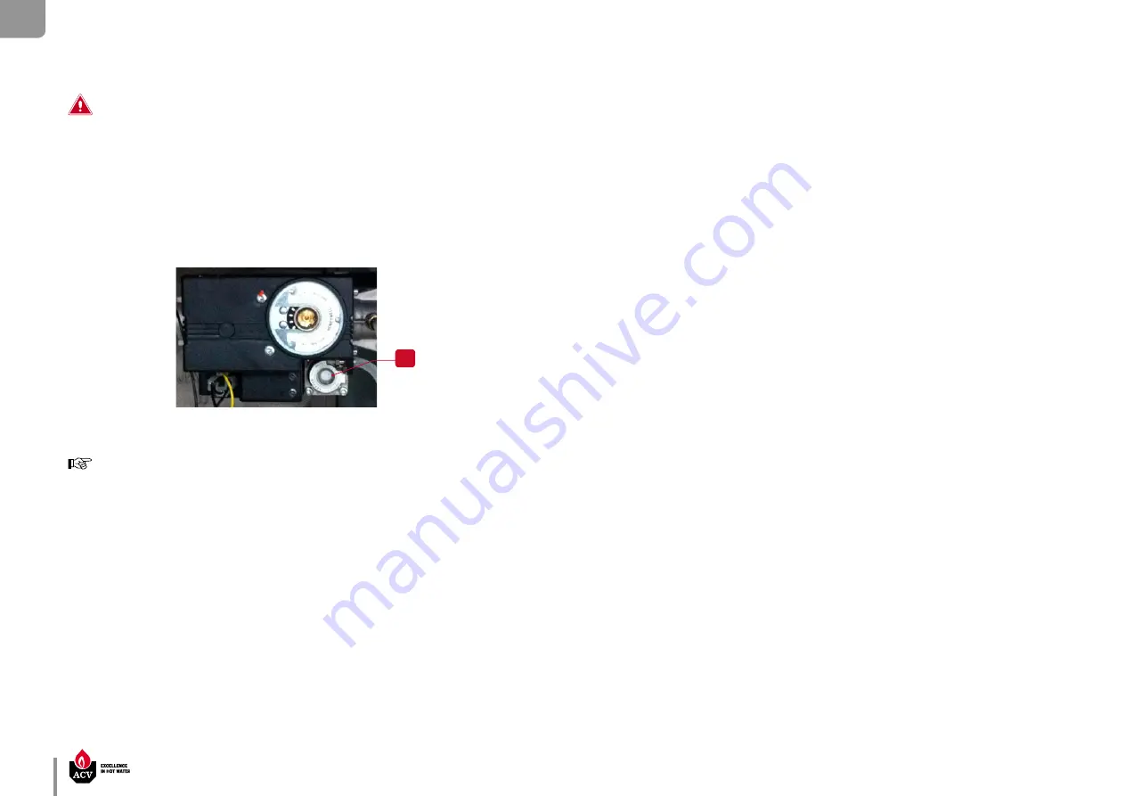
Do not change the OFFSET (A) setting of the gas valve: it is factory-preset and
sealed.
Essential recommendations for the correct operation of the appliance
•
Refer to the technical characteristics of this manual or to the burner
documentation to know the connection diameters.
•
Bleed the gas duct and check thoroughly if all the boiler tubes, both internal and
external, are tight.
•
Check the system gas pressure. Refer to the table containing all relevant data in
the section "Technical characteristics".
•
Check the boiler electrical connection, the boiler room air vent system, the
tightness of flue gas outlet pipes and of the burner chamber plate.
•
Control the gas pressure and consumption at appliance start up.
•
Check the boiler CO
2
adjustment (refer to the adjustment procedure and the
technical data).


