8
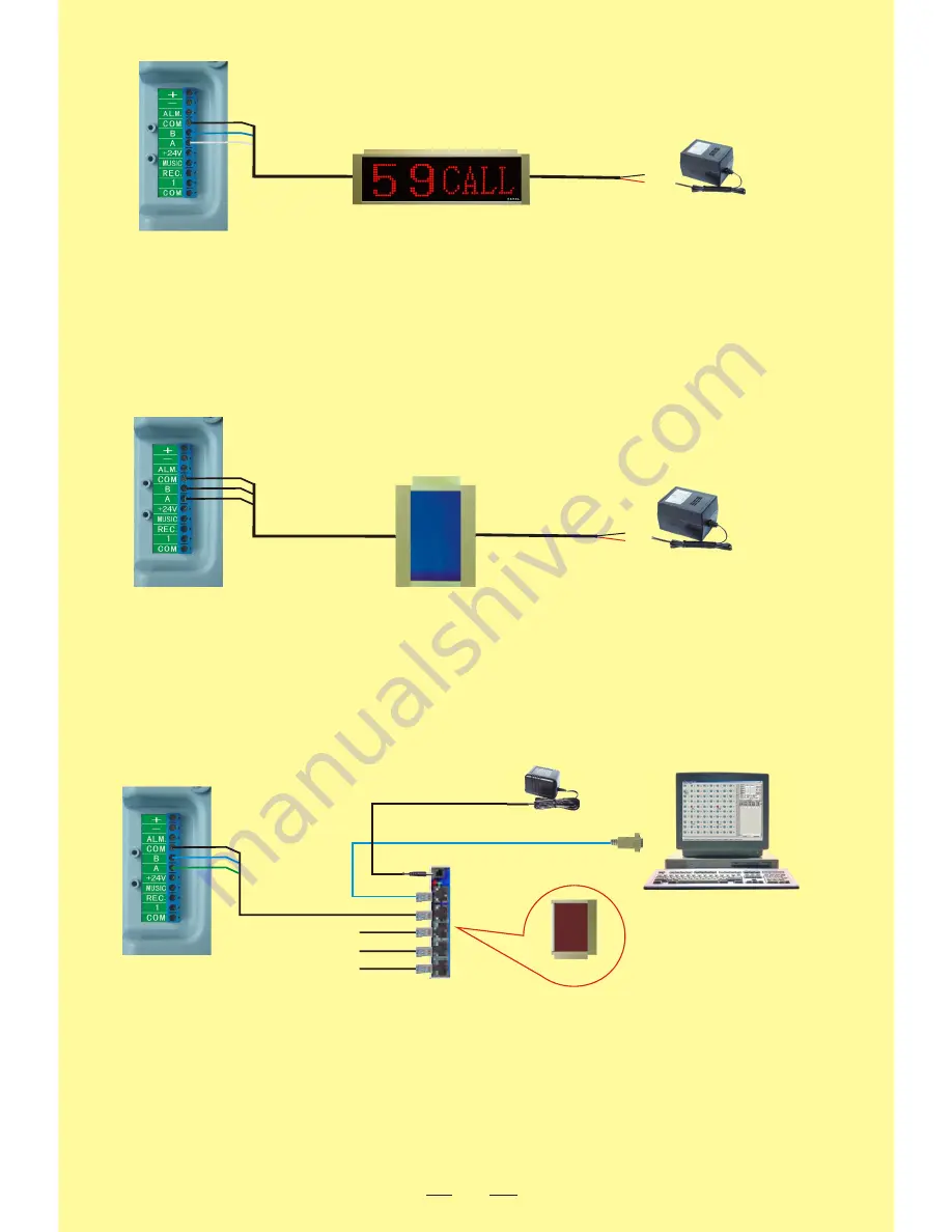
6. Corridor display and mainframe connection
7. Wireless transmitter and mainframe wiring
Wires for wireless transmitters are divided into two groups, one group is for power cord (+12V, COM), and the other
group is for data signal and power control cord (A, B, Ctr). Connect (+12V, COM) on the wireless transmitter
respectively to the positive and negative poles of the DC12V500mA; connect A, B, Ctr and COM on the wireless
transmitter respectively to A, B, Ctr and COM on the mainframe.
Wireless transmitter
3P
/
2P
/
+
-
There are two groups of wires for the corridor display, one group is for power cord (+12V and COM), while the other
group is for data signal and power control cord (A, B and Ctr). Respectively c12V and COM on the display
to the negative and positive poles of the DC12V500mA power supply. Connect A, B, Ctr and COM on the display
respectively to A, B, Ctr and COM on the mainframe.
Corridor display
+
-
3P
/
2P
/
8. Connection between monitoring statistics line concentration box, monitoring statistics
software, computer and mainframe
A. Insert the power cord into the line concentration box's power port.
B. Respectively insert the computer connecting line for the line concentration box (one terminal with 485/232 port
while the other with RJ45 port) into the 232 port and line concentration box of the computer according to the illustratio
n.
C. Connect the mainframe connecting lines (one terminal with RJ45 port while the other terminal with green, blue,
and black wires) respectively to the three binding posts (A, B and COM) of the line concentration box and mainfra
me.
D. In case of multiple mainframes connected to the line concentration box, refer to C.
To computer 232 port
Power source
Line concentration box port
3P
/
Monitoring statistics software
(self prepared computer)
To mainframe 2
Line concentration box
Power source
Power source
To mainframe 3
To mainframe 4
Mainframe rear diagram
Mainframe rear diagram
Mainframe rear diagram


